
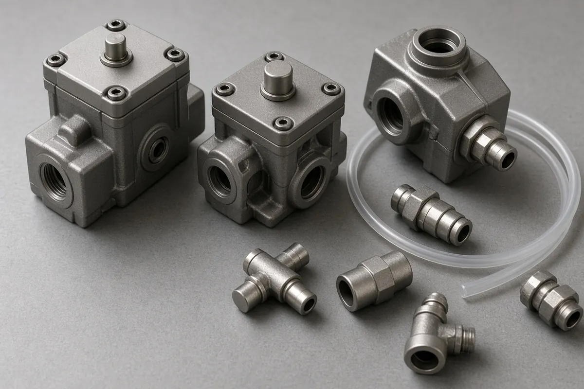
Sizing a double acting pneumatic cylinder requires matching effective extend and retract piston thrust (F_design = η × P × A), ISO 8778 free-air consumption (Q_ANR), end-of-stroke cushioning energy (E_k), and Euler column buckling stability (F_crit) against actual work-port pressure and payload kinematics. Selecting a bore from static shop-header pressure without deducting piston-rod area (6.3% to 16.0% pull loss), meter-out exhaust backpressure (30% to 50% dynamic force loss), or polyurethane (PU) tubing dead volume causes actuators to stall mid-stroke, slam aluminum end caps, buckle slender piston rods on long strokes, or waste 16% to 38% of compressed air on every cycle.
While our parent note on questions to write down before you size a cylinder inside the pneumatics section records the four field inputs from Josh Cosford’s vertical-lift worksheet (Pneumatic Tips: A designer’s guide to pneumatic cylinders)—load mass, work-port pressure after line drop, U-cup (> 20 in./s) versus O-ring seal speed limits, and mount alignment—this guide provides the quantitative pneumatic cylinder sizing calculations, a 10-bore ISO 6432 and ISO 15552 reference table at 6 bar, tubing dead-volume formulas, PPV versus PPS cushioning comparisons, Euler buckling checks, and rodless pneumatic cylinder selection criteria.
| Actuator Family & Standard | Bore Range (D) |
Typical Stroke Range (S) |
Force Symmetry (Extend vs. Retract) | Cushioning Architecture | Buckling & Side-Load Resistance | Primary Packaging Line Application |
|---|---|---|---|---|---|---|
Single-Acting Spring-Return (ISO 6432 / ISO 21287, 3/2 Valve) |
8–63 mm |
5–100 mm (limited by solid spring height) |
Powered one way; return spring subtracts 10%–30% of push thrust |
Fixed elastomer pads (P) |
Low; internal spring restricts stroke | Short-stroke gate stops, fail-safe clamp release, label tamping |
Mini Round Double-Acting (ISO 6432, 5/2 or 5/3 Valve) |
8, 10, 12, 16, 20, 25 mm |
10–500 mm |
Retract force is 14.1%–16.0% lower than extend (d / D = 0.375–0.40) |
Elastomer (P) standard; adjustable PPV on 16–25 mm |
Low (d = 4–10 mm); guide external side loads |
High-speed lane diverters, carton flap folders, light reject fingers |
Compact Profile Double-Acting (ISO 21287, 5/2 or 5/3 Valve) |
20, 25, 32, 40, 50, 63, 80, 100 mm |
5–200 mm (~50% shorter body than ISO 15552) |
Retract force is 10.1%–16.0% lower than extend |
Fixed elastomer (P) or self-adjusting (PPS) |
Moderate on short strokes; optional twin guide rods | Tight-envelope clamping, pouch sealing jaws, tray indexing stops |
Standard Profile / Tie-Rod Double-Acting (ISO 15552 / NFPA B93.15) |
32, 40, 50, 63, 80, 100, 125–320 mm (1.5–8 in.) |
25–2,000 mm (check Euler buckling > 500 mm) |
Retract force is 6.3%–16.0% lower than extend |
Adjustable pneumatic (PPV), self-adjusting (PPS), or external shock |
Subject to Euler buckling F_crit = π² E I / (K L)² on long strokes |
Case erectors, pusher transfers, vertical lifts, heavy reject rams |
Mechanically Coupled Rodless Cylinder (Slotted Tube, 5/2 or 5/3) |
16, 25, 32, 40, 50, 63, 80 mm |
100–6,000+ mm (~45%–50% footprint savings) |
100% symmetrical (d = 0; F_ext = F_ret = P × π D² / 4) |
Internal PPV / PPS plus external hydraulic shock absorbers |
Zero column buckling; integrated linear guide handles M_x, M_y, M_z moments |
Long-stroke case gantries, palletizer layer pushers, wide-belt shuttles |
Magnetically Coupled Rodless Cylinder (Hermetic Tube, 5/2 or 5/3) |
10, 16, 20, 25, 32, 40, 50, 63 mm |
50–3,000 mm (100% sealed stainless barrel) |
100% symmetrical (d = 0; capped by magnetic breakaway force) |
Elastomer (P) or adjustable pneumatic (PPV) |
Zero column buckling; carriage uncouples if inertia exceeds magnet limit | Washdown food/dairy conveyors, dusty powder fillers, cleanroom transfers |
1. Double-Acting Pneumatic Cylinder Mechanics, Valve Porting, and ISO Standards
A double acting pneumatic cylinder converts compressed air energy into controlled linear force in both travel directions (extend and retract). Unlike a single-acting cylinder (3/2 valve), which pressurizes only one chamber and loses 10% to 30% of its forward thrust compressing an internal helical return spring while limiting stroke length to <= 50–100 mm (The Engineering ToolBox: Pneumatic Cylinders — Force Exerted), a double-acting actuator seals both ends of the cylinder barrel and alternates compressed air between two work ports:
- Cap-End (Blind-End) Port (
Port 4): Pressurizing the rear cap chamber acts across the full circular piston face (A_cap = π × D² / 4), driving the piston rod outward on the extension (push) stroke while the rod chamber vents through a meter-out flow control valve. - Rod-End (Head-End) Port (
Port 2): Pressurizing the front head chamber acts across the ring-shaped annular area around the piston rod (A_annular = π × (D² − d²) / 4), pulling the rod home on the retraction (pull) stroke while the cap chamber exhausts.
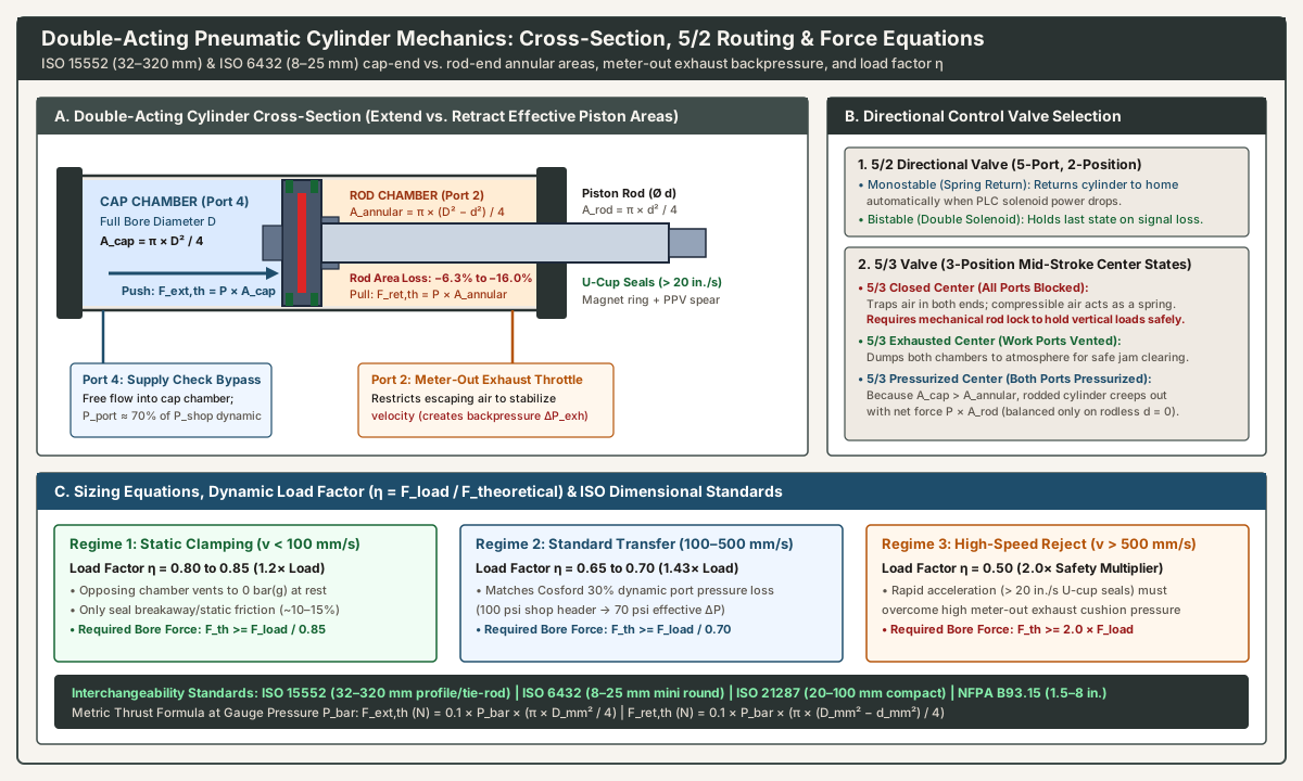
Directional Control Valve Selection: 5/2 Monostable, 5/2 Bistable, and 5/3 Center States
Double-acting cylinders are driven by 5-port directional solenoid valves (Port 1 supply, Ports 2 and 4 work ports, Ports 3 and 5 exhaust ports with throttle mufflers):
5/2Monostable (Single Solenoid, Spring Return): Shifts back to its home position automatically when PLC voltage drops.5/2Bistable (Double Solenoid, Detented): Holds its last commanded position during signal loss so transfer shuttles do not reverse mid-cycle.5/3Closed Center (All Ports Blocked): Traps air in both chambers when de-energized. As Josh Cosford warns in Pneumatic Tips: A designer’s guide to pneumatic cylinders, compressed air is compressible, so a closed-center valve or pilot check valve behaves like an air spring rather than a rigid hydraulic lock. Holding a vertical load safely requires a mechanical rod lock clamping cartridge, or an electric drive with a holding brake (pneumatic vs. servo motion).5/3Exhausted Center (Work Ports Vented): Vents both cylinder chambers to atmosphere so operators can move the carriage by hand during jam clearing.5/3Pressurized Center (Both Ports Pressurized): Applies supply pressurePto both ports simultaneously. BecauseA_cap > A_annularby the rod areaA_rod, a standard rodded cylinder still creeps outward with net forceF_creep = P × A_rodunless paired with a symmetrical through-rod orrodless pneumatic cylinder(d = 0).
Dimensional Interchangeability Standards (ISO 15552, ISO 6432, ISO 21287, NFPA)
Verify the dimensional standard on the machine drawing or existing nameplate (how to read an old pneumatics part number) so replacement cylinders remain drop-in interchangeable across manufacturers:
ISO 15552(SupersedingISO 6431/VDMA 24562) — Bores32, 40, 50, 63, 80, 100, 125–320 mm: Standardizes square end-cap envelopes, port threads (G1/8toG1), rod threads (M10×1.25toM27×2), barrel length, and detachable mounts (MS1foot,MF1/MF2flange,MP2clevis,MT4trunnion) across profile and tie-rod actuators (Rexroth/AVENTICSPRA/TRB, FestoDSBC, SMCCP96, ParkerP1D, NorgrenISOLine).ISO 6432— Miniature Round Cylinders in Bores8, 10, 12, 16, 20, 25 mm: Standardizes nose threads, rod threads, and rear-eye pivot center distances.ISO 21287— Compact Profile Cylinders in Bores20 to 100 mm: Cuts housing length by~50%versusISO 15552while matching32–100 mmend-cap bolt circles (note Cosford’s warning that older non-ISO compact cylinders remain vendor-specific).NFPA / ANSI B93.15— Inch Tie-Rod Cylinders in Bores1.5, 2.0, 2.5, 3.25, 4.0, 5.0, 6.0, 8.0 in.: North American square-head tie-rod standard (MX1,MF1,MP1,MS2,MT4mount codes).
2. Pneumatic Cylinder Force Equations, Rod-Area Deduction, and Dynamic Load Factors (η)
Exact Extend (Push) and Retract (Pull) Thrust Equations
Per The Engineering ToolBox: Pneumatic Cylinders — Force Exerted (Push and Pull), a double-acting cylinder with bore diameter D and piston rod diameter d has two different effective pressure areas:
- Cap-End Full Piston Area (
Extend / Push):A_cap = (π × D²) / 4 - Piston Rod Area:
A_rod = (π × d²) / 4 - Rod-End Annular Area (
Retract / Pull):A_annular = A_cap − A_rod = π × (D² − d²) / 4 - Metric Theoretical Force (
D, dinmm, Gauge PressureP_barinbar, Force inNewtons): Since1 bar = 100 kPa = 0.1 N/mm² = 10 N/cm²:F_ext,th (N) = 0.1 × P_bar × (π × D_mm² / 4) = 10 × P_bar × A_cap (cm²)F_ret,th (N) = 0.1 × P_bar × (π × (D_mm² − d_mm²) / 4) = 10 × P_bar × A_annular (cm²) - Imperial Theoretical Force (
D, dinin., PressureP_psiginpsig, Force inlbf):F_ext,th (lbf) = P_psig × (π × D_in² / 4)andF_ret,th (lbf) = P_psig × (π × (D_in² − d_in²) / 4)
On standard ISO 6432 and ISO 15552 cylinders, the rod occupies 6.3% (on 100 mm bore with 25 mm rod) to 16.0% (on 20, 25, 40, and 50 mm bores where d / D = 0.40) of the piston area. Whenever a cylinder pulls a load on retraction or lifts a vertical hoist mounted rod-down, you must size the bore using A_annular, not A_cap.
Friction, Meter-Out Backpressure, and the Three Dynamic Load Factor Regimes (η)
Theoretical force F_th is never available at the rod clevis during motion. First, piston seals, rod wipers, and guide bushings consume 5% to 15% in breakaway and sliding friction. Second, as Josh Cosford explains in Pneumatic Tips, upstream dryers and filters drop 4 to 12 psid (0.28 to 0.83 bar, detailed in our compressed air dryer selection guide), and meter-out flow controls throttle escaping exhaust air, creating opposing backpressure (20% to 40% pressure differential loss, or 30% mean rule of thumb where 100 psi shop air yields 70 psi effective differential; see our pneumatic flow control valve meter-out vs. meter-in sizing guide).
Industrial pneumatic cylinder sizing accounts for friction and exhaust backpressure via the load factor η (F_required,th >= F_load / η, or F_usable = η × F_th):
| Operating Velocity Regime | Load Factor (η) |
Safety Multiplier (1 / η) |
Physical Chamber State & Packaging Application Examples |
|---|---|---|---|
1. Static Clamping or Slow Pressing (v < 100 mm/s / < 4 in./s) |
η = 0.80 to 0.85 |
1.18× to 1.25× load |
Exhaust chamber vents to 0 bar(g) once the piston stops against the clamp or heat-seal bar; only static seal friction (~10%–15%) reduces thrust. |
2. Moderate Material Transfer (100 <= v <= 500 mm/s / 4–20 in./s) |
η = 0.65 to 0.70 |
1.43× to 1.54× load |
Matches Cosford’s 30% dynamic pressure-loss rule of thumb (100 psi shop air → 70 psi effective port differential) on case pushers, lifts, and diverters. |
3. High-Speed Packaging & Reject Rams (v > 500 mm/s / > 20 in./s, U-cup seals) |
η = 0.50 |
2.0× load (F_th >= 2 × F_load) |
Rapid acceleration must overcome high meter-out cushion pressure before exhaust air clears the tubing; mandatory for 200 container/min rams (reject actuator checklist). |
Worked Bore Sizing Examples: Imperial (NFPA) and Metric (ISO 15552)
- Cosford’s
500 lbfVertical Lift (NFPAImperial Series):- Naive Static Bore (
100 psig):A_cap = 500 lbf / 100 psig = 5.00 in.²→D = √(4 × 5.00 / π) = 2.523 in.. Stepping above the standard2.50 in.bore givesD = 3.25 in.(A_cap = 8.296 in.²). - Dynamic Check at
30%Loss (P_eff = 70 psig,η = 0.70):F_usable = 70 psig × 8.296 in.² = 580.7 lbf(580 lbfin Cosford’s guide). With only16%margin above the500 lbfweight, acceleration is sluggish; stepping to a4.0 in.bore (A_cap = 12.57 in.²,880 lbfat70 psig) ensures crisp vertical lift.
- Naive Static Bore (
- High-Speed Case Pusher (
ISO 15552Metric Series):- Load Force (
m = 35 kg,µ = 0.30,S = 400 mmin0.65 s,a = 2.8 m/s²,P = 5.5 bar):F_load = F_friction + F_inertia = (0.30 × 35 × 9.81) + (35 × 2.8) = 103.0 N + 98.0 N = 201.0 N. - Required Bore at
η = 0.50(v > 500 mm/s):F_ext,th >= 201.0 / 0.50 = 402.0 N→A_cap,min = 402.0 / (10 × 5.5) = 7.31 cm²(D_min = 30.5 mm). SelectD = 32 mm(A_cap = 8.04 cm²,442.3 Nat5.5 bar) orD = 40 mm(12.57 cm²) for higher rod stiffness and cushioning capacity.
- Load Force (
3. Master Lookup Table: ISO 6432 and ISO 15552 Force and Air Consumption at 6 bar (16–125 mm Bore)
The table below provides exact cap and annular areas, rod-area deduction, theoretical extend/retract forces at 6.0 bar (87 psig), high-speed usable forces at η = 0.50, and cylinder-only ISO 8778 free-air consumption (NL at compression ratio r = 6.923) per 100 mm of double stroke (100 mm extend + 100 mm retract). Scale force linearly for other pressures (× 0.667 at 4 bar, × 0.833 at 5 bar, × 1.167 at 7 bar).
Standard & Bore D (mm) |
Standard Rod d (mm) |
Cap Area A_cap (cm²) |
Annular Area A_annular (cm²) |
Rod Area Loss (%) |
Theoretical Extend Force at 6 bar (N) |
Theoretical Retract Force at 6 bar (N) |
Dynamic 50% Extend (η = 0.50, N) |
Dynamic 50% Retract (η = 0.50, N) |
Free Air per 100 mm Double Stroke at 6 bar (NL) |
|---|---|---|---|---|---|---|---|---|---|
ISO 6432 — 16 mm |
6 mm |
2.01 |
1.73 |
-14.1% |
120.6 N (27.1 lbf) |
103.7 N (23.3 lbf) |
60.3 N |
51.8 N |
0.259 NL |
ISO 6432 — 20 mm |
8 mm |
3.14 |
2.64 |
-16.0% |
188.5 N (42.4 lbf) |
158.3 N (35.6 lbf) |
94.2 N |
79.2 N |
0.400 NL |
ISO 6432 — 25 mm |
10 mm |
4.91 |
4.12 |
-16.0% |
294.5 N (66.2 lbf) |
247.4 N (55.6 lbf) |
147.3 N |
123.7 N |
0.625 NL |
ISO 15552 — 32 mm |
12 mm |
8.04 |
6.91 |
-14.1% |
482.5 N (108.5 lbf) |
414.7 N (93.2 lbf) |
241.3 N |
207.3 N |
1.035 NL |
ISO 15552 — 40 mm |
16 mm |
12.57 |
10.56 |
-16.0% |
754.0 N (169.5 lbf) |
633.3 N (142.4 lbf) |
377.0 N |
316.7 N |
1.601 NL |
ISO 15552 — 50 mm |
20 mm |
19.63 |
16.49 |
-16.0% |
1,178.1 N (264.8 lbf) |
989.6 N (222.5 lbf) |
589.0 N |
494.8 N |
2.501 NL |
ISO 15552 — 63 mm |
20 mm |
31.17 |
28.03 |
-10.1% |
1,870.3 N (420.5 lbf) |
1,681.9 N (378.1 lbf) |
935.2 N |
840.9 N |
4.099 NL |
ISO 15552 — 80 mm |
25 mm |
50.27 |
45.36 |
-9.8% |
3,015.9 N (678.0 lbf) |
2,721.4 N (611.8 lbf) |
1,508.0 N |
1,360.7 N |
6.620 NL |
ISO 15552 — 100 mm |
25 mm |
78.54 |
73.63 |
-6.3% |
4,712.4 N (1,059.4 lbf) |
4,417.9 N (993.2 lbf) |
2,356.2 N |
2,208.9 N |
10.535 NL |
ISO 15552 — 125 mm |
32 mm |
122.72 |
114.68 |
-6.6% |
7,363.1 N (1,655.3 lbf) |
6,880.6 N (1,546.8 lbf) |
3,681.6 N |
3,440.3 N |
16.435 NL |
Stepping up one standard ISO 15552 bore size (such as 50 mm to 63 mm) increases air consumption by 63.9% on every stroke. Never oversize cylinder bores arbitrarily when a lower load factor or higher port pressure solves the problem.
4. Free-Air Consumption (ISO 8778 ANR) and the Polyurethane Tubing Dead-Volume Penalty
Under ISO 8778 Standard Reference Atmosphere (ANR), free air is referenced at P_atm = 1.01325 bar(a) (101.325 kPa), T_ANR = 20 °C (68 °F), and 65% RH. Compressing atmospheric air to gauge pressure P_bar multiplies its volume by the compression ratio r:
r = (P_bar + 1.013) / 1.013 (at P_bar = 6.0 bar, r = 7.013 / 1.013 = 6.923)
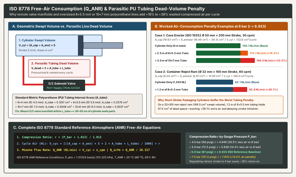
Double-Stroke Free-Air Formula Including Parasitic Tubing Dead Volume (V_dead)
Every time a 5/2 directional valve shifts, it must pressurize not only the cylinder chamber (A × S) but also the full length L_tube of polyurethane (PU) tubing between the valve manifold and the cylinder port (A_tube × L_tube), and then vent that entire tube volume to atmosphere on the return half-cycle. For areas in cm² and lengths S, L_tube in cm:
- Free Air per Double Stroke (
NL/cycle):V_cycle (NL) = [ ((A_cap + A_annular) × S + 2 × A_tube × L_tube) / 1000 ] × ((P_bar + 1.013) / 1.013) - Continuous Volumetric Flow Rate (
NL/minandscfmatncycles/min):Q_ANR (NL/min) = V_cycle × nandQ_scfm = Q_ANR / 28.317 - Peak Instantaneous Valve Flow Rate (
Q_peakduring stroke durationt_extendwith Cosford’s0.70acceleration factor):Q_peak,ext (NL/min) = [ ((A_cap × S + A_tube × L_tube) / 1000) × r ] × (60 / (0.70 × t_extend_sec))
Standard metric PU tubing internal cross-sectional areas (A_tube = π × d_ID² / 4) and dead volumes are:
6 × 4 mm(ID = 4.0 mm):A_tube = 0.1257 cm²(12.6 cm³/mper line;0.174 NL/cycleper meter of pair at6 bar)8 × 5.5 mm(ID = 5.5 mm):A_tube = 0.2376 cm²(23.8 cm³/mper line;0.329 NL/cycleper meter of pair at6 bar)10 × 7 mm(ID = 7.0 mm):A_tube = 0.3848 cm²(38.5 cm³/mper line;0.533 NL/cycleper meter of pair at6 bar)12 × 8 mm(ID = 8.0 mm):A_tube = 0.5027 cm²(50.3 cm³/mper line;0.696 NL/cycleper meter of pair at6 bar)
Worked Packaging Air-Penalty Examples at 6 bar (r = 6.923)
- Case Erector Transfer Cylinder (
ISO 15552,D = 50 mm,d = 20 mm,S = 20 cm,n = 30 cpm):- Cylinder-Only Volume:
(19.635 + 16.493) × 20 = 722.6 cm³→5.002 NL/cycle(150.1 NL/min/5.30 scfm). - With
2.5 m(250 cm) of8 × 5.5 mmTubing per Port:V_dead = 2 × 0.2376 × 250 = 118.8 cm³(+16.4%parasitic loss), raising demand to5.825 NL/cycle(174.7 NL/min/6.17 scfm). - With
3.0 m(300 cm) of10 × 7 mmTubing:V_dead = 2 × 0.3848 × 300 = 230.9 cm³(+32.0%parasitic loss), raising demand to6.601 NL/cycle(198.0 NL/min/6.99 scfm).
- Cylinder-Only Volume:
- High-Speed Container Reject Ram (
ISO 15552,D = 32 mm,d = 12 mm,S = 10 cm,n = 60 cpm):- Cylinder-Only Volume:
(8.042 + 6.912) × 10 = 149.5 cm³→1.035 NL/cycle(62.1 NL/min). - With
1.2 m(120 cm) of8 × 5.5 mmTubing per Port:V_dead = 2 × 0.2376 × 120 = 57.0 cm³(+38.1%parasitic air penalty,1.430 NL/cycle/85.8 NL/min), while adding pneumatic lag on a200 container/minstation (reject actuator checklist).
- Cylinder-Only Volume:
Per the U.S. DOE / Compressed Air Challenge Sourcebook, mounting valve manifolds within 30 to 50 cm of the cylinder and installing a 2.5 to 3.0 bar check-regulator on the unloaded return port cuts actuator air demand by 25% to 45%. During a plant compressed-air leak survey, label 5/2 valve exhaust mufflers as intentional cyclic vents, and verify that stationary cylinders show zero continuous exhaust blow-by.
5. End-of-Stroke Cushioning (P vs. PPV vs. PPS) and Euler Column Buckling (F_crit)
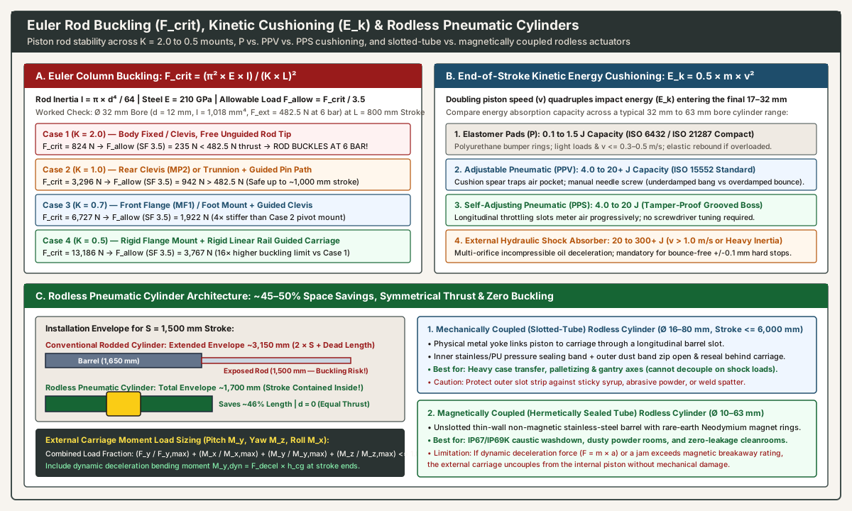
End-of-Stroke Kinetic Energy (E_k = 0.5 × m × v²) and Cushioning Selection
At the end of each stroke, the cylinder cushion must decelerate the moving mass m_total (kg) from terminal impact velocity v_impact (m/s, typically 1.3× to 1.5× average speed S / t):
E_k (J) = 0.5 × m_total × v_impact²
Because E_k scales with v_impact², doubling piston speed quadruples impact energy (Pneumatic Tips: Self-adjusting cushioning for pneumatic cylinders and Power & Motion: All About Cylinder Cushioning):
| Cushioning Architecture | Mechanism | Energy Capacity (32–63 mm Bore) |
Tuning & Operational Characteristics | Dominant Failure Mode |
|---|---|---|---|---|
1. Fixed Elastomer Pads (P) |
Flexible polyurethane (TPU) or nitrile (NBR) buffer rings on the piston faces. |
0.1 to 1.5 J (~0.4 J on 32 mm; ~1.2 J on 63 mm) |
Zero adjustment; compact housing (standard on ISO 6432 and ISO 21287). |
Elastic Rebound: Above v = 0.3–0.5 m/s or with heavy loads, pads deform elastically and bounce the piston backward. |
2. Adjustable Pneumatic (PPV) |
Piston cushion spear traps an air pocket over the last 17 to 32 mm of travel and bleeds it through a manual needle screw. |
4.0 to 20+ J (~4.5 J on 32 mm; ~10 J on 50 mm; ~18 J on 63 mm) |
Screwdriver-tuned under full load and pressure (standard on ISO 15552). |
Underdamped Bang vs. Overdamped Bounce: Too open slams the head cap; too closed causes piston bounce-back and 100–300 ms hesitation. |
3. Self-Adjusting Pneumatic (PPS) |
Longitudinal throttling grooves machined along the cushion boss vent trapped air progressively as the piston advances. | 4.0 to 20 J (matches PPV across 80% of applications) |
Zero commissioning screws; tamper-proof and adapts automatically to moderate load/pressure shifts. | Boundary Saturation: Cannot be manually closed down for extreme slow/heavy combinations outside its groove profile. |
| 4. External Hydraulic Shock Absorber | Multi-orifice oil damper mounted on a rigid external stop block (constant linear deceleration force over 10–50 mm). |
20 to 300+ J per cycle |
Mandatory when E_k exceeds PPV/PPS limits (v > 1.0 m/s) or for bounce-free ±0.1 mm hard stops. |
Stop Slip: If the external stop slips so the cylinder piston bottoms out first, the aluminum head cracks. |
Euler Column Buckling Limit (F_crit) Across Four Mounting Cases (K = 2.0 to 0.5)
As Cosford notes in Pneumatic Tips, strokes longer than ~30 in. (760 mm) expose standard piston rods to Euler column buckling during extension, and rear pivot mounts (clevis MP2) lengthen the unsupported column. With rod area moment of inertia I = (π × d⁴) / 64 (mm⁴), steel modulus E = 210,000 N/mm² (210 GPa), free stroke length L (mm), and safety factor SF = 3.5:
F_crit = (π² × E × I) / (K × L)² and F_allow = F_crit / 3.5 >= F_ext,th
Evaluating an ISO 15552 32 mm bore cylinder (d = 12 mm rod, I = 1,017.9 mm⁴, F_ext,th = 482.5 N at 6 bar) at an L = 800 mm stroke:
| Mounting Configuration & Euler Case | Euler Factor (K) |
Critical Load F_crit (32×800 mm) |
Allowable Thrust F_allow (SF = 3.5) |
Engineering Verdict at 6 bar (482.5 N Push Thrust) |
|---|---|---|---|---|
| Case 1: Body Fixed or Clevis + Free Unguided Rod Tip | K = 2.0 |
824 N |
235 N |
FAILS (235 N < 482.5 N): Rod buckles laterally at 6 bar, scoring the rod bushing and jamming the barrel. |
Case 2: Rear Clevis (MP2) or Trunnion (MT4) + Guided Pin |
K = 1.0 |
3,296 N |
942 N |
PASSES (942 N > 482.5 N): Safe up to ~1,050 mm stroke when guided in one plane without side loads. |
Case 3: Front Flange (MF1) or Foot (MS1) + Guided Clevis |
K = 0.7 |
6,727 N |
1,922 N |
PASSES (1,922 N > 482.5 N): Rigid flange mount doubles buckling capacity compared to rear clevis (Case 2). |
| Case 4: Rigid Flange/Foot + Rigid Linear Ball-Rail Carriage | K = 0.5 |
13,186 N |
3,767 N |
PASSES (3,767 N > 482.5 N): Use a self-aligning rod coupler to prevent parallel rail misalignment from binding the rod seal. |
6. Rodless Pneumatic Cylinder Selection: Slotted-Tube vs. Magnetically Coupled
When stroke length exceeds 500 to 760 mm, machine guards cannot fit the 2 × Stroke extended envelope of a rodded cylinder, or an external carriage must carry eccentric bending moments, a rodless pneumatic cylinder provides four structural advantages (Pneumatic Tips: How do pneumatic rodless cylinders, slides work? and Power & Motion: Right-Sizing Rodless Pneumatic Actuators; for a 5-year TCO and mechanical comparison of rodless cylinders against toothed-belt and ball-screw electric linear actuators, see our pneumatic vs. electric actuator TCO and changeover guide):
45% to 50%Footprint Reduction: A1,500 mmstroke rodded cylinder requires~3,150 mmwhen extended (2 × S + dead length). A rodless cylinder contains the stroke inside its barrel (~1,700 mmoverall length).100%Symmetrical Push/Pull Thrust (d = 0): With no piston rod (A_rod = 0), both chambers use the full bore areaA = π × D² / 4, delivering identical force in both directions.- Zero Column Buckling (
Strokes up to 6,000+ mm): No rod enters axial compression; intermediateT-slotbrackets support the aluminum extrusion every500 to 800 mm. - Integrated Linear Guidance for Pitch (
M_y), Yaw (M_z), and Roll (M_x) Moments: Size the external carriage guide so the combined load fraction satisfies:L_combined = (F_y / F_y,max) + (F_z / F_z,max) + (M_x / M_x,max) + (M_y / M_y,max) + (M_z / M_z,max) <= 1.0Always include the dynamic pitch momentM_y,dyn = m_load × a_decel × h_cgduring end-of-stroke cushioning.
| Feature | Mechanically Coupled Rodless Cylinder (Slotted Tube) | Magnetically Coupled Rodless Cylinder (Hermetic Tube) |
|---|---|---|
| Coupling & Sealing Design | Metal yoke links piston to carriage through a longitudinal barrel slot sealed by an inner stainless/PU pressure band and an outer dust strip. | Unslotted thin-wall stainless-steel tube; rare-earth (NdFeB) magnet rings couple piston to carriage across the sealed wall. |
| Bore & Stroke Range | 16–80 mm bore; strokes 100 to 6,000+ mm. |
10–63 mm bore; strokes 50 to 3,000 mm. |
| Overload & Leak Behavior | Positive mechanical yoke cannot decouple under shock load; minuscule band seepage requires a mechanical brake for vertical holding. | 100% hermetically sealed (zero slot leakage), but carriage uncouples if dynamic inertia (F = m × a) or a jam exceeds magnetic breakaway force. |
| Best Packaging Environment | Heavy dry case transfer, palletizers, and wide gantry shuttles (specify stainless outer bands near dust or weld spatter). | IP67/IP69K caustic washdown food/dairy, dusty powder filling, and cleanrooms where slotted barrels trap debris. |
Six-Step Pneumatic Cylinder Sizing Verification Sequence
- Record Load (
F_load) and Governing Stroke: UseA_annular = π × (D² − d²) / 4whenever retraction pulls or lifts the load (cylinder selection questions). - Apply Load Factor (
η): Useη = 0.85(static< 100 mm/s),η = 0.70(transfer100–500 mm/s), orη = 0.50(> 500 mm/spackaging). - Select Standard
ISO 6432orISO 15552Bore: Pick the smallest bore satisfyingF_th >= F_load / ηat minimum FRL pressure. - Verify Euler Buckling (
F_crit / 3.5 >= F_ext,th): Check push strokes> 300–500 mm; switch to a rodless pneumatic cylinder when buckling or2 × Senvelope limits are exceeded. - Check Cushioning (
E_k = 0.5 × m × v_impact²): SpecifyPPSor tunedPPVcushions up to4–20 J, and external hydraulic shocks above catalog limits. - Budget
ISO 8778Air Consumption (Q_ANR) and Purity: Include2 × A_tube × L_tubedead volume, mount5/2valves within30–50 cmof ports, and maintainISO 8573-1:2010 [2:4:2]air quality (air preparation questions for a packaging line).