
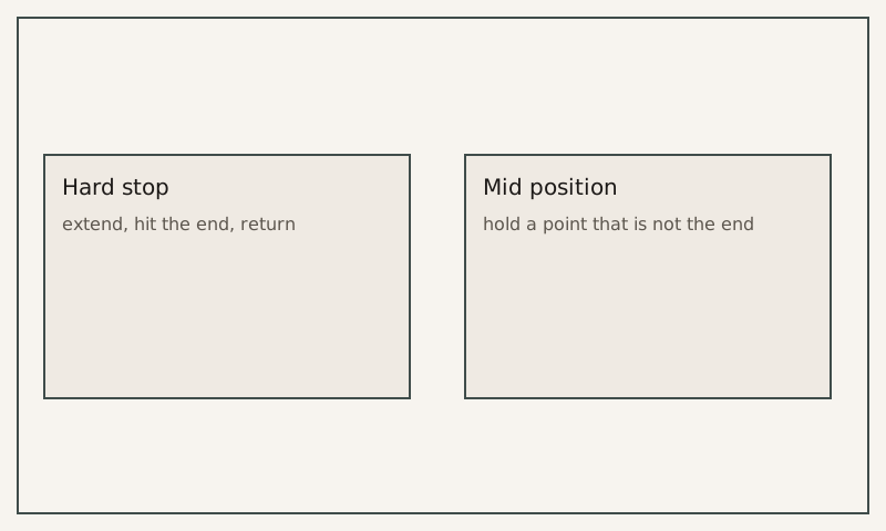
Using a servo for a push that only has to hit a hard stop wastes a drive, and using air for a stop that has to hold a tight position can miss when the air compresses. Compare the job in front of you. One actuator does not stand in for the other.
This page is based on public documents, not a test by this site. The cylinder side is Josh Cosford’s “A designer’s guide to pneumatic cylinders” (Pneumatic Tips, 26 January 2026; library copy fetched 9 October 2026). The electric side is Sara Jensen in Power & Motion on 18 September 2023 (library copy fetched 8 October 2026). Both were read on 15 October 2026.
The packaging lines section also holds the reject checklist. Bore inputs are on the cylinder page.
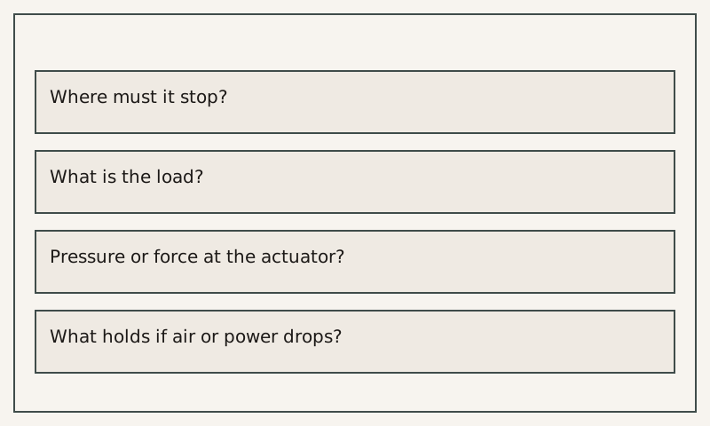
| Question | Air cylinder | Servo |
|---|---|---|
| Where must it stop? | Hard end, or a mid point | Hard end, or a mid point |
| What is the load? | Your measurement | Your measurement |
| What pressure or force is at the actuator? | Port pressure, not the shop gauge | The limit the drive is set to |
| What holds if air or power drops? | Rod lock, guide, or nothing | Brake, screw, or nothing |
A stop at the end, or a stop in the middle
Cosford sizes a pneumatic cylinder from load, pressure differential, stroke and mount. In his account a U-cup cylinder can be expected to run at over 20 inches per second, and an O-ring cylinder at about half that, sometimes slower. That speed is why air is used for a short push. It is also why he says the seals fail first when the velocity exceeds what the design allows.
Jensen reports one gripper that inserts coils into MRI magnets. The insertion tolerance in that account is no more than 0.5 mm. The coils weigh up to 1.5 tonnes. The robot’s load capacity is given as 2,300 kg. Electric actuators were chosen over pneumatics, she writes, because that application needed free positioning and a clamp that does not let the coils move. The company told the magazine that pneumatics would not be stiff enough for those results. She calls quieter, more precise positioning a common benefit described for electric versus pneumatic technologies, and she reports strokes of up to 500 mm on the actuators used there. A servo drive on that robot can command a defined speed and a limited force.
Those sentences describe one machine and one manufacturer’s explanation to the magazine. They do not say a servo can take every air cylinder off a packaging line.
Holding the load
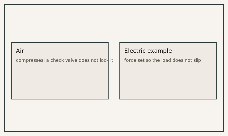
Cosford writes that air compresses, so a pilot-operated check valve will not hold a load safely the way it can in hydraulics. A rod lock has to clamp the rod. Jensen’s coil job is the other report: the electric supports were chosen because the force could be set and the coils must not twist or slip. If your station only has to reach a hard stop and come back, compressibility is a cushioning problem on that station. It is not, by itself, a reason to change the drive.
What to write for each motion
Use Cosford’s warning if the station is pneumatic: shop pressure is not the pressure at the piston once the valve, the line and any meter-out back pressure are included. Use Jensen’s 0.5 mm only as the tolerance reported for that coil insertion. A reject ram that fires and returns is the checklist. The air that feeds a pneumatic station is the preparation note.