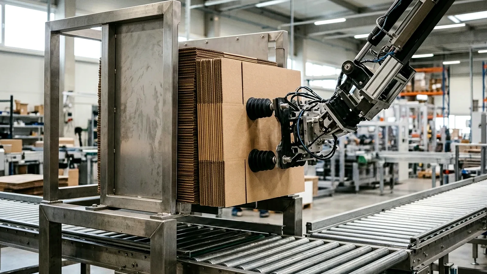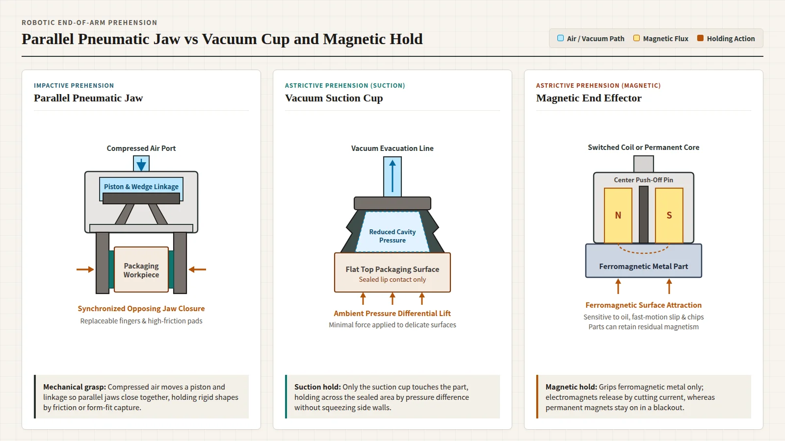
Industrial robotic grippers may employ mechanical, suction, or magnetic means: impactive jaws physically grasp parts by direct contact and friction, astrictive suction cups hold across a sealed face while applying minimal surface force, and magnetic grippers hold only ferromagnetic material. Check workpiece permeability, contact force, acceleration, and the separate wrist plate before choosing.
What Is a Robotic Gripper and How Are Mechanisms Classified?
In robotics, an end effector (or tool head) sits at the end of a robotic arm to interact with the working environment, typically as a gripper or a tool. Typical applications of industrial robots include welding, painting, assembly, disassembly, pick and place, packaging and labeling, palletizing, product inspection, and testing. Across packaging line applications, end-of-arm selection sits beside upstream axis choices in pneumatic vs servo motion, drive ownership comparisons in pneumatic vs electric actuator TCO and changeover, and downstream verification in the reject actuator checklist.
Wikipedia groups robotic prehension into four general categories:
- Impactive grippers: Jaws or claws that physically grasp by direct impact upon the object; Fluid Power Journal similarly defines a mechanical gripper by jaws that open and close to grasp an object.
- Ingressive grippers: Pins, needles, or hackles that physically penetrate the object surface, used in textile, carbon, and glass fiber handling.
- Astrictive grippers: Attractive forces applied to the object surface, whether by pneumatic suction, magnetoadhesion, or electroadhesion.
- Contigutive grippers: Direct-contact adhesion methods such as glue, surface tension, or freezing.
In industrial practice, grippers employ mechanical, suction, or magnetic means, while vacuum cups and electromagnets dominate the automotive field and metal sheet handling.
Jaw, Vacuum Cup, or Magnet: Which Mechanism Fits the Workpiece?
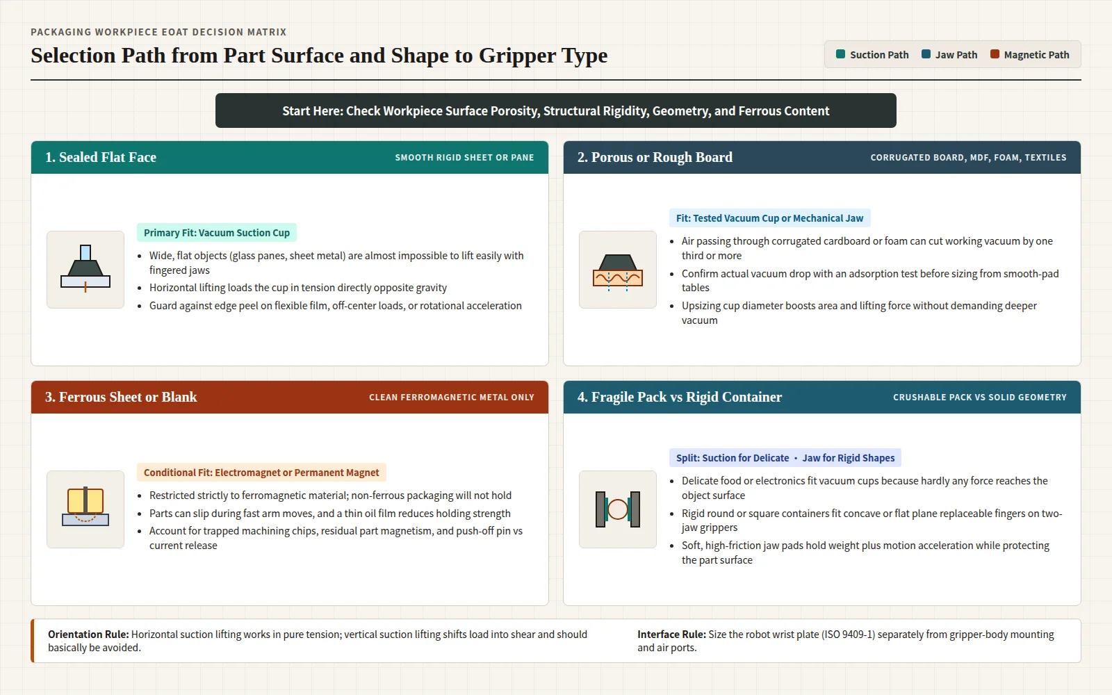
Workpiece surface porosity, structural rigidity, geometry, and ferrous content set the boundary between mechanical jaws, vacuum cups, and magnets.
| Gripper mechanism | Prehension category | How the part is held | Fitting workpieces | Primary failure boundaries |
|---|---|---|---|---|
| Pneumatic jaw (parallel or angular) | Impactive mechanical | Compressed air drives a piston and wedge or linkage so jaws close on the object, holding by frictional force or form-fit capture | Rigid round or square containers and tasks using replaceable concave or plane two-finger jaws | Hard jaws without a soft high-friction lining can damage object surfaces; keeping minimum clamping force during a pressure drop requires a mechanical gripping-force maintenance version |
| Vacuum suction cup | Astrictive pneumatic | Pressure difference between ambient air and reduced cup cavity pressure acts across the effective sealing area | Delicate food or electronics and wide, flat objects such as glass panes or sheet metal | Permeable corrugated cardboard, MDF, raw wood, foam, and textiles pass air and drop working vacuum; vertical shear loading and edge peel cause rapid release |
| Electromagnet or permanent magnet | Astrictive magnetic | Switched coil current or an always-on permanent magnet applies magnetic attraction to the part face | Ferromagnetic metal sheets and parts only | Cannot hold non-ferromagnetic material; parts can slip when moved quickly, surface oil reduces strength, machining chips cling on unload, and parts can stay magnetised |
In a Robotiq vacuum-gripper note, the suction cup is the only part touching the manipulated object and applies hardly any force to the surface, suiting delicate food or electronics as well as wide, flat panes of glass or sheet metal that are almost impossible to lift easily with a fingered gripper. When vacuum is chosen, compare ejector versus pump air supply in Venturi ejector vs rotary vacuum pump for pick-and-place.
How Do Pneumatic Parallel and Angular Jaws Hold Parts?
Two-finger grippers tend to be used for industrial robots performing specific tasks in less-complex applications, and their fingers are replaceable. Finger geometry follows part contour: a concave impression suits a round object, whereas a flat plane suits a square shape. Although several forces act on a lifted body, the main force is frictional force, and the robotic gripper must withstand both the weight of the object and acceleration from frequent movement; making the gripping surface from a soft material with a high coefficient of friction protects the object surface from damage.
Synchronized parallel and angular jaw transmissions
In Fluid Power Journal’s pneumatic-gripper overview, parallel grippers are the most widely used style: the jaws remain parallel during the full stroke, usually in a two-jaw configuration, driven by a piston and piston rod connected to a mechanical linkage or wedge cam so both jaws open and close at the same speed and keep the object centered. Schunk’s PGN-plus-P series datasheet likewise describes a compressed-air piston whose angled wedge-hook active surfaces produce synchronized, parallel jaw motion.
In the Bosch Rexroth AVENTICS pneumatic grippers brochure, parallel grippers open and close in a synchronized, parallel movement suited to both inner and outer gripping, whereas angular grippers suit opening angles up to 40 degrees and use involute gears to maintain a constant gripping moment across the angle range. Across AVENTICS GSP-P sizes 08, 10, 16, 20, 25, and 40, that brochure lists a total gripping-force range of 26 to 840 N, maximum workpiece mass of 0.13 to 4.2 kg, and stroke per finger of 2 to 13 mm.
Worked jaw force check and catalog boundaries
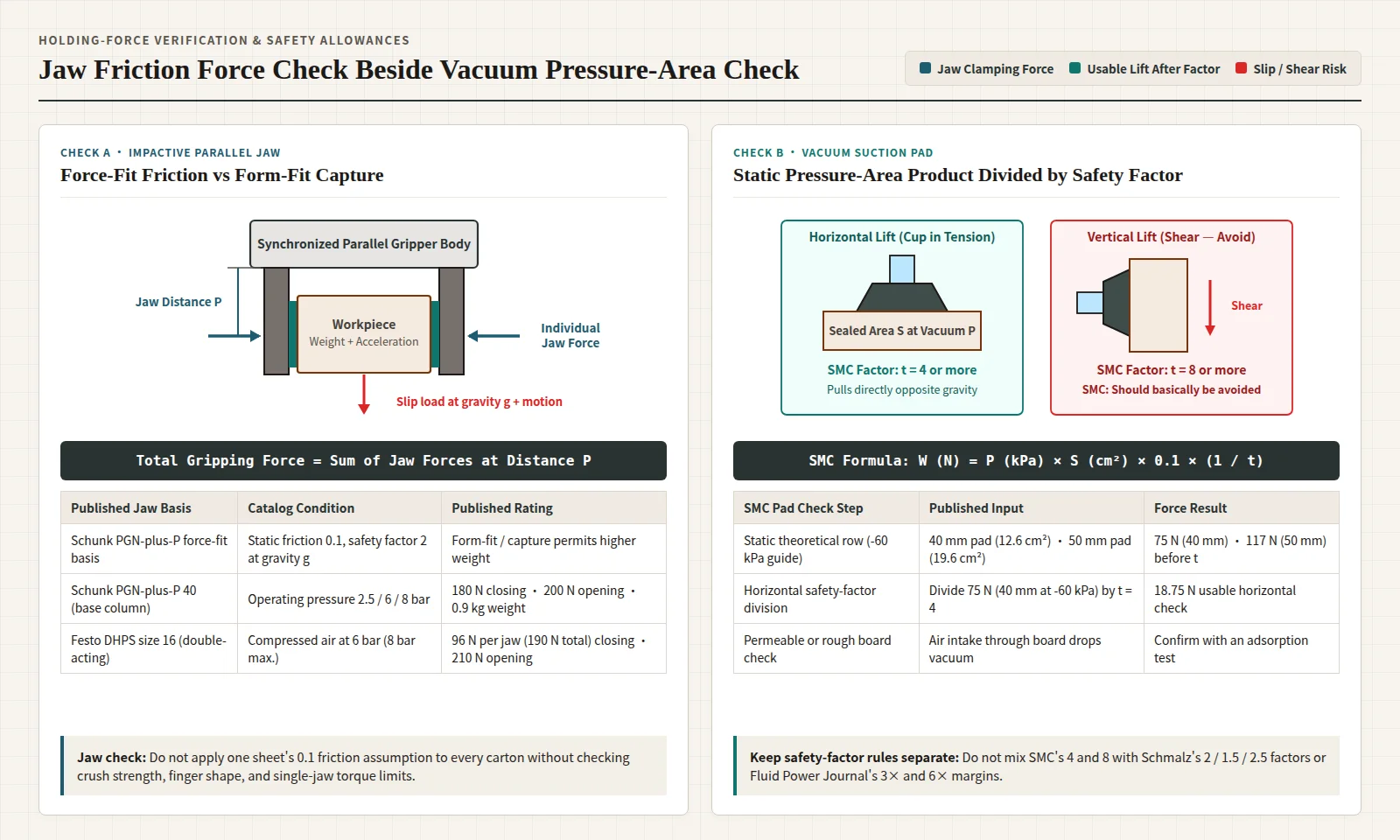
Schunk defines total gripping force as the arithmetic sum of the individual force applied to each jaw at distance P. For force-fit gripping, Schunk calculates permissible workpiece weight with a coefficient of static friction of 0.1 and a safety factor of 2 against workpiece slippage at acceleration due to gravity g, noting that form-fit or capture gripping permits significantly higher workpiece weights.
- Schunk PGN-plus-P 40 base column: Lists closing/opening force of 180/200 N, recommended workpiece weight of 0.9 kg, and min./nom./max. operating pressure of 2.5/6/8 bar (keep this separate from the spring-assisted AS column at 235 N closing and IS column at 260 N opening).
- Festo DHPS parallel, double-acting 2-jaw series: At 6 bar (with 8 bar maximum operating pressure), size 16 delivers 96 N closing force per jaw (190 N total) and 105 N opening force per jaw (210 N total), with 0.02 mm repetition accuracy defined as end-position drift over 100 consecutive strokes and permissible torques stated per single jaw. Its operating medium is compressed air to ISO 8573-1:2010 [7:4:4]; class rules sit in air preparation for packaging lines.
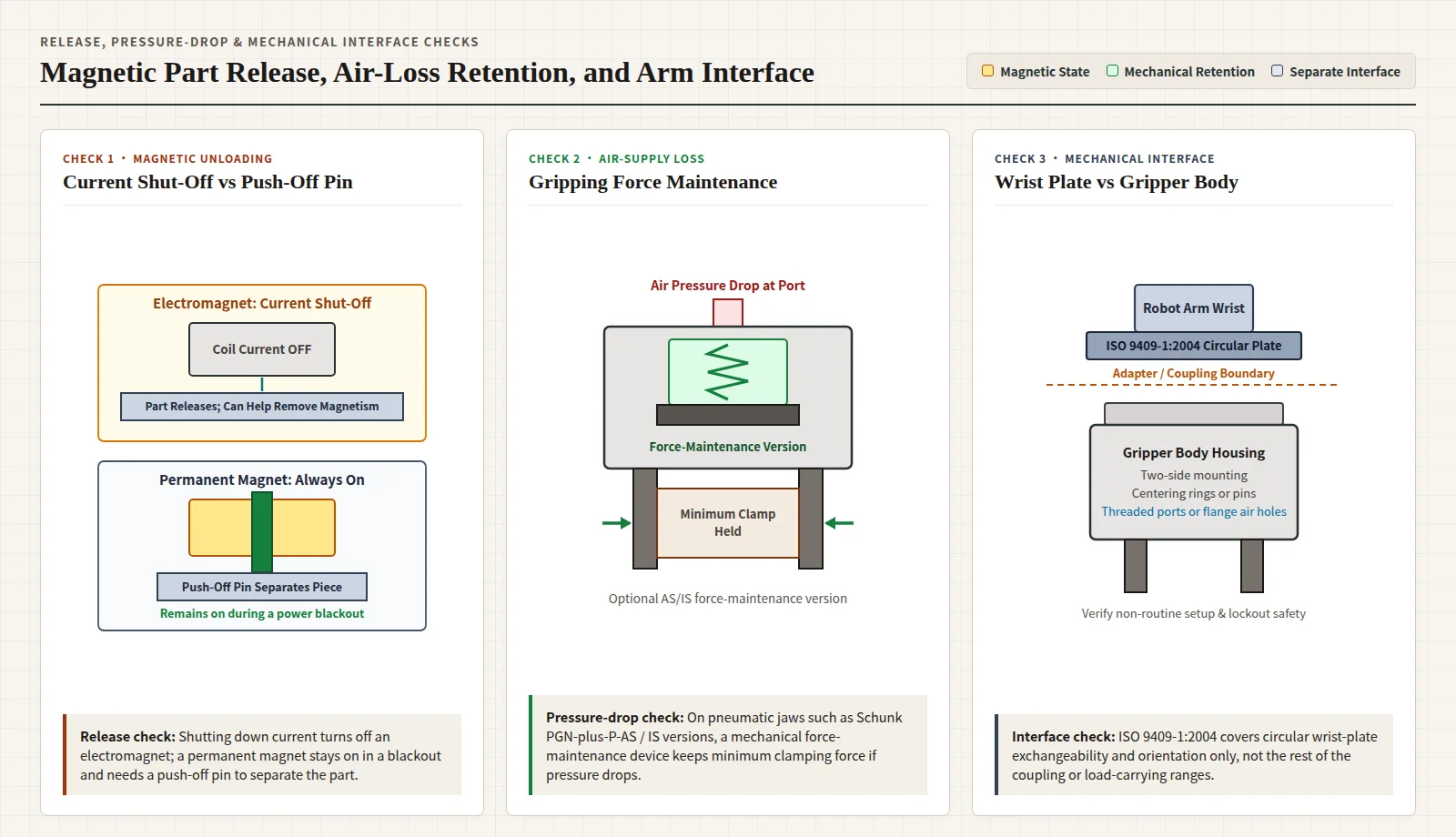
- Air-loss clamping retention: On Schunk variants equipped with a mechanical gripping-force maintenance device, a minimum clamping force stays applied even if air pressure drops.
How Do Vacuum Suction Cups Hold Porous or Flat Packaging?
SMC states that theoretical lifting force is determined by vacuum pressure and vacuum-pad contact area: doubling vacuum pressure doubles theoretical lifting force, while doubling pad diameter quadruples theoretical lifting force. Because theoretical lifting force is measured in the static state, the safety factor for actual operating conditions must be estimated in operation. Schmalz writes static holding force without a safety factor as F = delta-p × A (ambient-to-system pressure difference times effective suction area), and Piab writes F = A × P in newtons with circular cup area A in m² (pi × Diam² / 4) and vacuum pressure P in Pa (N/m²).
Worked SMC pad calculation and orientation limits
SMC gives approximately -60 kPa as a vacuum-pressure guide when an ejector is used and writes usable lifting force W in N as W = P × S × 0.1 × (1 / t), where P is vacuum pressure in kPa, S is pad area in cm², theoretical lifting force before safety factor equals P × S × 0.1, and safety factor t is 4 or more for horizontal lifting and 8 or more for vertical lifting. Beside its vertical-lifting sketch, SMC prints that vertical lifting should basically be avoided.
In the SMC pad table, the 40 mm pad column has 12.6 cm² area and lists 75 N theoretical force on the -60 kPa row, while the 50 mm column has 19.6 cm² area and lists 117 N on that same -60 kPa row. Dividing the 75 N theoretical lifting force by a horizontal safety factor of 4 gives 18.75 N for that horizontal check. Piab’s corrugated-board example shows why cup diameter matters: on a 40 mm cup, dropping vacuum pressure from 65 kPa to 55 kPa cuts lifting force by about 15 percent, whereas stepping up from a 40 mm cup to a 50 mm cup at 55 kPa increases lifting force by more than 35 percent.
Porosity loss, cup peel, and vendor safety-factor rules
Published safety factors and porosity allowances stay anchored to each source rather than merged across formulas:
- Porous packaging materials: Fluid Power Journal notes that the ideal vacuum-times-area product assumes perfect sealing, no leakage, no motion, and full vacuum, whereas corrugated cardboard, MDF, raw wood, foam, and textiles pass air through the material and may reduce working vacuum levels by one third or more; SMC specifies running an adsorption test to confirm vacuum drop on permeable or rough workpieces.
- Tension, shear, and peel: In Fluid Power Journal, horizontal lifting pulls directly against gravity in tension, vertical lifting shifts the load into shear, and lifting one cup edge lets air enter the sealing zone so vacuum collapses rapidly—peel being common on flexible materials, off-center loads, or high rotational acceleration. That article states margins of 3 times theoretical holding force for smooth horizontal lifting and 6 times or higher for porous materials, vertical handling, or high-speed automation.
- Schmalz safety factors and friction trial rule: Schmalz recommends a safety factor of at least 2, cites a German UVV binding safety factor of 1.5, and specifies 2.5 or higher when swiveling workpieces; its horizontal pickup calculation example yields an 8.85 cm cup diameter (1.12 × √((50 kg × 2) ÷ (0.4 bar × 4))) for a 50 kg plastic sheet at -0.4 bar across 4 cups with safety factor 2 (printing a measured friction coefficient of 0.5 alongside), and notes that cup-to-workpiece friction coefficients are not generally valid and have to be determined through trials.
What Are the Limits of Magnetic Robotic Grippers?
Magnetic prehension belongs to the astrictive family alongside suction, and electromagnets share metal-sheet handling duties in automotive plants. However, Robotiq’s magnetic end-effector note lists five practical constraints that restrict packaging use:
- Ferromagnetic material only: A magnetic end effector can only be used with ferromagnetic material.
- Fast-motion slip and oil sensitivity: When moved quickly, the part can slip out of the end effector, and even a little oil on the surface can reduce holding strength.
- Chip carry-over and residual magnetism: Machining chips can stay on the gripper during unloading, and handled parts can remain magnetised.
Release behavior differs between coil-driven and permanent designs. In the same Robotiq note, shutting down electrical current turns off an electromagnet’s attraction and can help remove magnetism from the handled part, whereas permanent magnets are always on, stay active during a power blackout, and rely on an integrated push-off pin to separate the piece from the magnet.
How Does a Gripper Mount on the Arm and Meet Safety Rules?
Mechanical mounting splits into the robot’s distal wrist flange and the gripper housing itself. Published as Edition 3 (2004-03) and last reviewed and confirmed in 2023 so that this version remains current, ISO 9409-1:2004 defines the main dimensions, designation, and marking for a circular plate mechanical interface to ensure exchangeability and keep the orientation of hand-mounted end effectors. Its public abstract states that the standard does not define other requirements of the end-effector coupling device and contains no correlation of load-carrying ranges, leaving interface selection to the application and the robot’s load-carrying capacity. Separately, on the gripper housing, the Bosch Rexroth AVENTICS brochure describes mounting from two sides with centering rings or pins and feeding compressed air through two threaded ports or additional flange-connection holes.
Robot cell guarding and collaborative force standards
For personnel working around packaging cells, OSHA’s robotics overview states that there are currently no specific OSHA standards for the robotics industry, and notes that many robot accidents occur during programming, maintenance, testing, setup, or adjustment when a worker may be inside the robot’s working envelope. On OSHA’s robotics standards page, OSHA lists 1910 Subpart O and 1910.212 for machinery and machine guarding alongside 1910.147 for the control of hazardous energy (lockout/tagout).
Consensus robot-system standards explicitly include end-of-arm tooling:
- System and EOAT integration: OSHA notes that ANSI/RIA R15.06-2012 is the U.S. National Adoption of ISO 10218-1,2:2011, describes ISO 10218-2 as covering safe integration of an industrial robot system including end-effectors, and describes ISO/TR 20218-1 as safety design for end-effectors (EOAT) in collaborative or non-collaborative industrial environments.
- Collaborative force verification: RIA TR R15.606 is the U.S. National Adoption of ISO/TS 15066:2016, while RIA TR R15.806 describes testing methods to verify that collaborative system forces remain within TR 606 limits. On ISO’s public record, ISO/TS 15066:2016 supplements ISO 10218-1 and ISO 10218-2 for industrial robot systems (excluding non-industrial robots and collaborative applications designed prior to its publication); it was last reviewed and confirmed in 2022 so that it remains current, while its life-cycle table also marks stage 90.92 on 2025-06-26 as an International Standard to be revised for replacement by ISO/AWI 15066-1 under development.
Packaging Robotic Gripper Selection Checklist
Before releasing an end-of-arm tooling specification for a carton erector, case packer, or palletizing cell, verify and record six station checks:
- Workpiece surface and material class: Record whether the contact zone is a rigid square or round body, a wide flat non-porous sheet, delicate food or electronics, permeable corrugated board or foam, or clean ferromagnetic metal.
- Prehension mechanism and contact protection: Pair rigid parts with replaceable concave or plane jaws (adding a soft high-friction lining where surface damage is a risk), pair sealed flat or delicate packs with suction cups, and restrict magnetic tooling to clean ferromagnetic parts where fast-motion slip, oil, chips, and residual magnetism are acceptable.
- Dynamic holding force and safety factor: Size jaws for object weight plus motion acceleration (checking whether force-fit friction or form-fit capture applies), or size suction pads by dividing static pressure-area force by the chosen method’s horizontal safety factor while avoiding vertical shear picks and edge peel—confirming porous-board vacuum loss with an adsorption test.
- Power-loss and air-drop behavior: Check whether air-driven jaws need a mechanical gripping-force maintenance version to hold minimum clamping force during a pressure drop, and distinguish electromagnet current shut-off from always-on permanent magnets with push-off pins.
- Wrist interface vs gripper body ports: Match the robot wrist circular plate under ISO 9409-1:2004 to robot load capacity and adapter geometry separately from two-side gripper body mounting, centering rings or pins, and threaded or flange compressed-air ports.
- Non-routine setup and guarding controls: Apply 1910.212 machine guarding, 1910.147 lockout/tagout during jaw changes or teach-pendant setup inside the working envelope, ISO 10218-2 / ISO/TR 20218-1 EOAT integration checks, and TR R15.806 / ISO/TS 15066:2016 force verification on collaborative cells.