
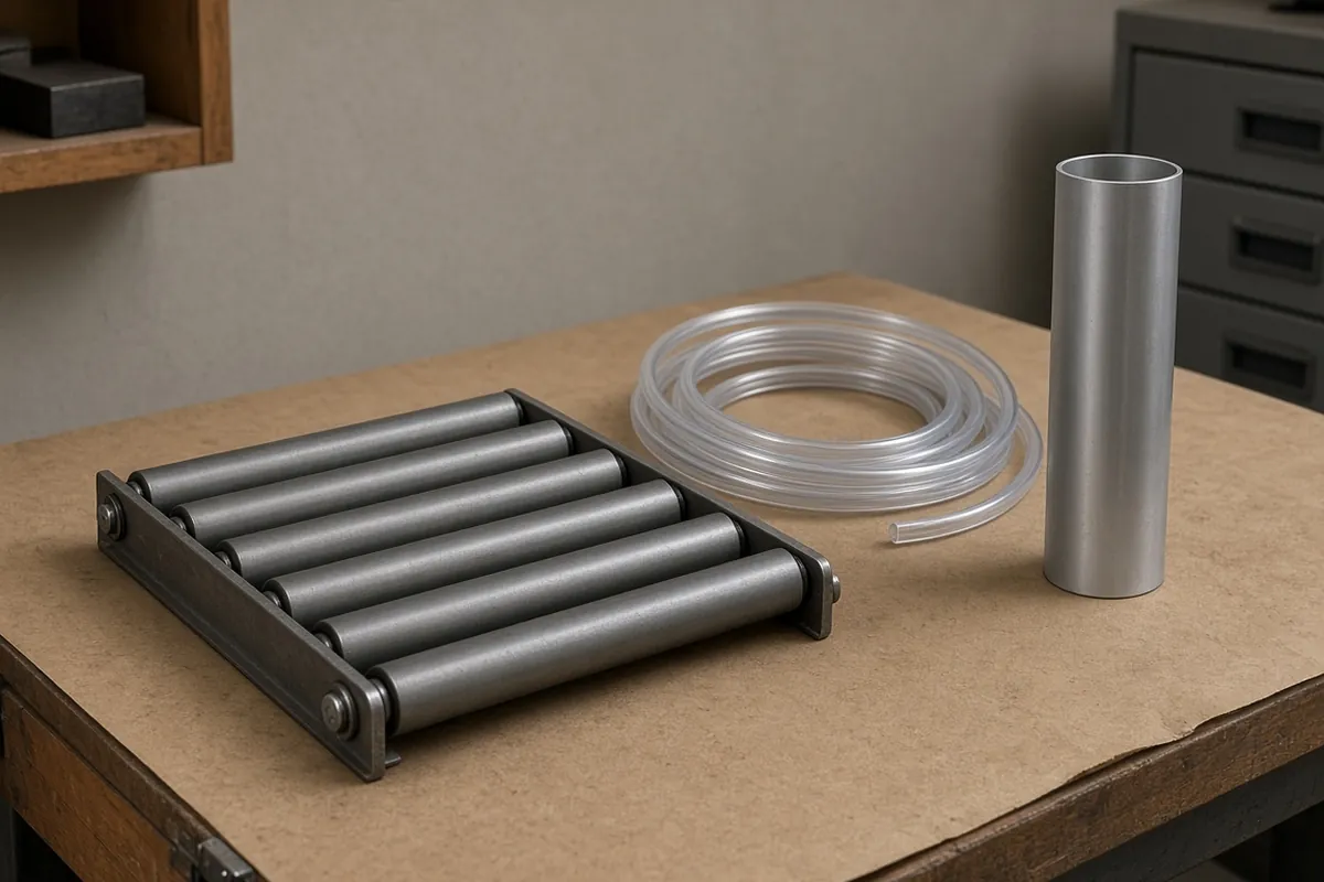
Evaluating a pneumatic vs electric actuator for a packaging machine station requires calculating the 5-year Total Cost of Ownership (TCO_5yr), wall-to-shaft thermodynamic energy efficiency (8% to 18% for compressed air versus 65% to 82% for electromechanical drives), multi-SKU format changeover downtime (servo vs pneumatic changeover), and long-stroke linear mechanics (rodless pneumatic cylinder versus toothed-belt and ball-screw axes). Comparing hardware strictly by initial purchase price (USD 250 to 650 for a pneumatic cylinder and 5/2 valve slice versus USD 850 to 4,200 for an electric linear axis) obscures two opposite engineering mistakes: installing a USD 2,500 servo drive on a short-stroke, low-duty 2-position stop that consumes less than USD 15/yr in compressed air (> 60-year payback), or installing a large-bore pneumatic pusher on a 3-shift, multi-SKU case packer where USD 900 to 1,800/yr in compressed air, seal rebuilds, and manual stop-collar changeover downtime exceeds the servo capital premium in less than 3 to 18 months.
While our parent note on when a packaging motion is air, and when it is a servo inside the packaging lines section contrasts Josh Cosford’s hard-stop cylinder rules (Pneumatic Tips: A designer’s guide to pneumatic cylinders) against Sara Jensen’s 0.5 mm tolerance, 1.5-tonne MRI coil assembly gripper report (Power & Motion: Electric Actuators Improve Robotic Assembly of MRI Machines) and sets out four baseline questions per station, this engineering reference supplies the quantitative pneumatic vs electric actuator TCO equations, wall-to-shaft energy loss cascades, three worked packaging station payback benchmarks, PackML recipe changeover OEE math, and a mechanical comparison of slotted and magnetically coupled rodless pneumatic cylinder drives against electric toothed-belt and ISO 3408 ball-screw actuators.
| Actuator Architecture & Standard | Hardware CapEx per Axis (USD) |
Wall-to-Shaft Energy Efficiency (η_sys) |
Positional Capability & Repeatability | Practical Stroke (S) & Max Speed (v_max) |
Service Life (km) & Maintenance Interval |
Optimal Packaging Line Station Profile |
|---|---|---|---|---|---|---|
Standard Rodded Pneumatic Cylinder (ISO 6432 / ISO 15552 + 5/2 Valve) |
USD 250–650 (USD 420 typical 32–50 mm bore) |
8%–18% (~12% plant mean; 0 W during static clamp dwell) |
2 fixed hard stops (±0.10 mm at end caps; 3–4 stops with tandem cylinder) |
10–1,000 mm (Euler buckling check > 500 mm); 0.1–1.5 m/s (> 20 in./s U-cup) |
3,000–8,000 km (U-cup seal & PPV cushion kit USD 60–140) |
Short-stroke (<= 100 mm), low-duty (<= 10 cpm) 2-position stops, clamps, and 200 cpm binary reject rams (reject actuator checklist) |
Slotted or Magnetic Rodless Pneumatic Cylinder (d = 0 Symmetrical) |
USD 550–950 (USD 820 typical 40–63 mm bore) |
8%–18% (+25%–40% savings if fitted with 3 bar return regulator) |
2 fixed hard stops (±0.10–0.15 mm at end stops with hydraulic shocks) |
100–6,000+ mm (saves 45%–50% footprint vs. rodded; zero buckling); 1.5–3.0 m/s |
2,000–5,000 km (slotted inner/outer bands USD 120–280; magnetic 3,000–6,000 km) |
Long-stroke (> 600 mm) 2-position transfers at low-to-moderate duty, or IP69K washdown / ATEX explosion-proof zones (magnetic tube) |
Simplified IO-Link Electric Cylinder (24–48 VDC Stepper / BLDC + Screw/Belt) |
USD 850–1,500 (integrated drive; no cabinet amplifier) |
60%–75% (FOC closed-loop stepper + ball screw or belt) |
2 to 32 PLC recipe coordinates (±0.02–0.05 mm); adjustable speed & force |
50–800 mm; 0.15–0.80 m/s (thrust 100 to 3,000 N) |
8,000–15,000 km (re-grease screw every 2,500–5,000 km) |
Multi-SKU guide-rail width adjusters, case magazine stops, and medium-duty pushers replacing manual stop collars |
Full Servo Ball-Screw / Roller-Screw Axis (ISO 3408 + 400/480 VAC PMSM) |
USD 1,800–4,200 (USD 2,150–3,100 typical packaging axis) |
65%–80% (85%–90% ball screw; 80%–85% planetary roller screw) |
Infinite PackML / OPC UA coordinates (±0.005–0.030 mm); S-curve jerk & I_q torque limit |
50–1,500 mm (capped by screw whip speed n_crit ∝ d_r / L²); 0.3–1.5 m/s |
10,000–25,000+ km (ISO 3408-5 L_10 = (C_a / F_m)³ × 10⁶ rev) |
Continuous 2–3 shift case erector pushers, vertical flighted elevators, precision carton loaders, and high-force servo presses |
Full Servo Toothed-Belt Linear Axis (AT5 / AT10 / STD8 Steel-Cord Belt) |
USD 2,200–4,500 (USD 2,950 typical 600–2,000 mm shuttle) |
70%–82% (90%–95% belt mechanical transmission efficiency) |
Infinite recipe coordinates (±0.05–0.10 mm); full S-curve synchronization |
100–10,000+ mm (zero screw whip); 2.0–5.0+ m/s (a_max = 20–50 m/s²) |
15,000–30,000+ km (3×–8× rodless pneumatic band life) |
High-duty 2–3 shift long-stroke (> 600 mm) transfer shuttles, palletizer layer gantries, and flying-saw / conveyor tracking axes |
1. Wall-to-Shaft Energy Efficiency Cascade: Why Pneumatics Delivers 8%–18% vs. 65%–82% for Electric Actuators
Across industrial energy audits published in the U.S. Department of Energy and Compressed Air Challenge Sourcebook, Festo EnEffAH (Energy Efficiency in Production in the Drive and Handling Technology Sector) research, and Linear Motion Tips: Electric actuators vs. pneumatic cylinders: Total cost of ownership, compressed air actuation converts only 8% to 18% (~10% to 14% typical plant average) of electrical input power at the compressor motor terminals into useful mechanical work at the cylinder piston rod. By contrast, an electromechanical linear actuator driven by a pulse-width-modulated (PWM) servo or closed-loop stepper amplifier achieves 65% to 82% (~75% typical) wall-to-shaft efficiency—a 5× to 7× thermodynamic efficiency advantage during continuous cycling.
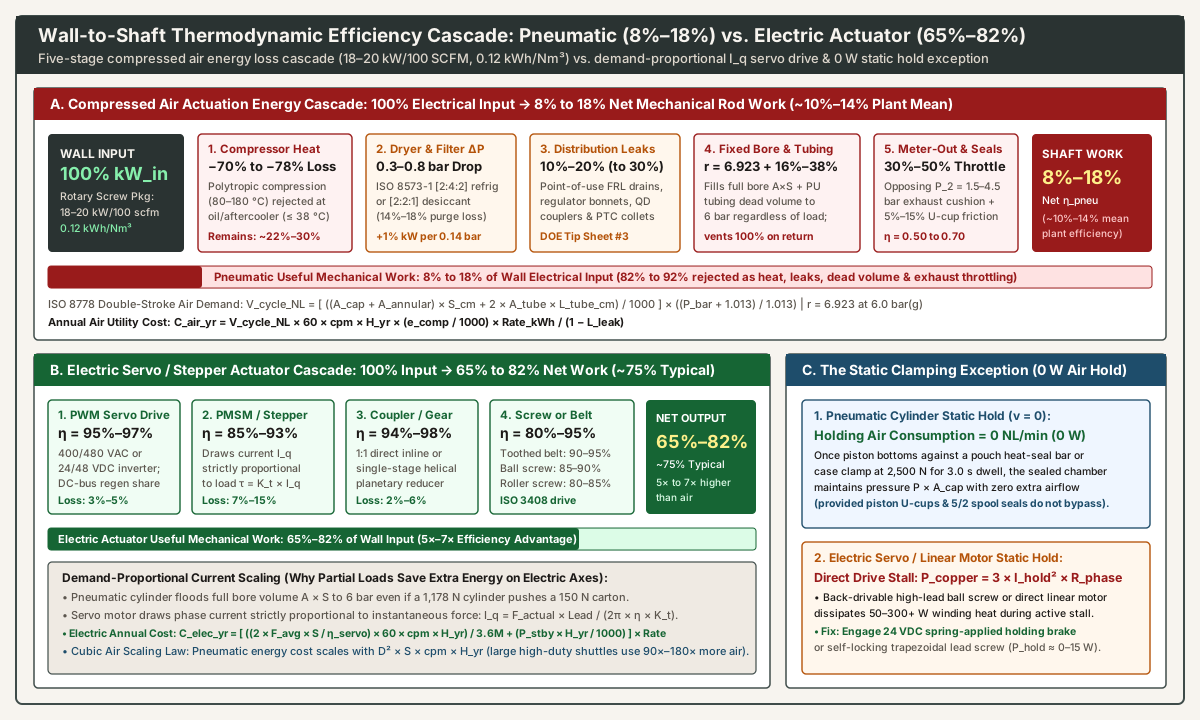
The Five-Stage Pneumatic Energy Loss Cascade (100% kW_in → 8%–18% Rod Work)
Tracing 100% of the electrical kilowatt-hours fed into a plant’s rotary screw compressor package (specific power = 18 to 20 kW per 100 SCFM, equivalent to e_comp = 0.106 to 0.125 kWh/Nm³ at 6.5 to 7.0 bar(g)) reveals five compounding physical losses before the piston rod moves a carton:
- Stage 1 — Polytropic Compression Heat Rejection at the Compressor (
70% to 78%Loss): Compressing ambient air (P_atm = 1.013 bar(a),20 °C) to7.0–8.0 bar(g)(100–115 psig) inside an oil-flooded or oil-free rotary screw airend raises gas temperature to80–180 °C. Because downstream point-of-useFRLbowls, polyurethane tubing, and dryers require inlet air cooled to<= 38 °C(100 °F), the compressor oil cooler and aftercooler reject70% to 78%of total electrical shaft input energy directly to ambient air or cooling water as waste heat before the compressed air ever leaves the compressor room. Only22% to 30%of the electrical input remains as pneumatic pressure-volume (P × V) potential energy in the main receiver. - Stage 2 — Air Drying and Coalescing Filtration Overhead (
ΔP = 0.3 to 0.8 bar/4 to 12 psid,2% to 15%Loss): Conditioning compressed air to meet packaging line purity standards (air preparation questions for a packaging line) requires either anISO 8573-1:2010 [2:4:2]refrigerated dryer (+0.6 to 0.8 kW/100 SCFMchiller load and0.28 to 0.55 barpressure drop across pre/post coalescing filters) or anISO 8573-1 [2:2:1]twin-tower heatless desiccant dryer (14% to 18%compressed air purge loss plus0.41 to 0.83 barfilter/bed drop, detailed in our compressed air dryer selection: refrigerated vs. desiccant guide). Every0.14 bar(2 psi) of treatment pressure drop increases compressor shaft power by+1.0%. - Stage 3 — Distribution Ring-Main and Point-of-Use FRL Leaks (
L_leak = 10% to 30%Loss): As quantified in U.S. DOE Tip Sheet #3 and our compressed air leak detection and ultrasonic survey ROI guide, unmaintained facilities lose20% to 30%of total compressor output to choked sonic leaks across jammedFRL unitfloat drains, weepingISO 6953regulator bonnets, worn quick-disconnect (QD) couplers, and side-loaded push-to-connect (PTC) tube collets. Even a plant executing quarterly40 kHzultrasonic surveys carries a residualL_leak = 8% to 15%baseline leakage fraction. - Stage 4 — Irreversible Fixed-Volume Chamber Filling and Polyurethane Tubing Dead Volume (
25% to 50%Over-Pressurization Loss): An electric servo motor draws torque-producing current strictly proportional to instantaneous payload resistance (I_q = τ / K_t). A double-acting pneumatic cylinder, by contrast, is a fixed-displacement constant-pressure expansion chamber. Even if anISO 1555250 mmbore cylinder (theoretical push force F_ext,th = 1,178.1 Nat6.0 bar) is pushing a light5 kgcorrugated case requiring only150 Nof thrust, the5/2directional valve still floods the entire swept cylinder bore (A_cap × Son extend andA_annular × Son retract) plus both connecting polyurethane (PU) tubes (2 × A_tube × L_tube, which adds+16.4% to +38.1%parasitic dead volume per cycle; see our double-acting pneumatic cylinder force and air consumption guide) all the way up to full6.0 bar(g)line pressure (compression ratio r = 6.923) at the end of every stroke—and then dumps100%of that pressurized air to atmosphere through the exhaust muffler on the return stroke. - Stage 5 — Meter-Out Exhaust Throttling Backpressure and Seal Friction (
30% to 50%Dynamic Work Deduction): As Josh Cosford details in Pneumatic Tips: A designer’s guide to pneumatic cylinders (referenced on our cylinder selection questions page) and our pneumatic flow control valve meter-out vs. meter-in sizing guide, preventing stick-slip piston chatter requires meter-out exhaust throttling. Restricting the escaping exhaust air intentionally trapsP_2 = 1.5 to 4.5 bar(g)of opposing backpressure in the venting chamber (matching Cosford’s30%dynamic pressure-loss rule of thumb on moderate transfersη = 0.70, and50%loss on high-speed packaging ramsη = 0.50), alongside5% to 15%elastomericU-cuporO-ringsliding seal friction.
Multiplying the surviving energy fractions across all five stages (0.26 compressor × 0.94 dryer/filter × 0.85 leak survival × 0.65 partial-load/dead-volume utilization × 0.70 meter-out dynamic factor) yields 9.5% to 14.5% (8% to 18% operating band) net wall-to-shaft efficiency.
The Four-Stage Electric Actuator Efficiency Cascade (100% kW_in → 65%–82% Shaft Work)
An electromechanical linear axis—combining a solid-state servo or stepper drive, a brushless motor, a coupler or reducer, and a mechanical screw or belt transmission (Linear Motion Tips: Linear actuators: Pneumatic or electric?)—converts electrical input into linear thrust across four low-loss stages:
- Stage 1 — Pulse-Width-Modulated (
PWM) Servo Amplifier / Inverter (η_drive = 95% to 97%): A400/480 VACthree-phase or24/48 VDCdecentralized IGBT/MOSFET servo drive converts line power into vector-controlled stator phase currents with only3% to 5%switching and conduction loss, while sharing regenerative deceleration energy (0.5 × m × v²) across a common multi-axis DC bus. - Stage 2 — Permanent-Magnet Synchronous Motor (
PMSM) or Closed-Loop Stepper (η_motor = 85% to 93%): Rare-earth (NdFeB) brushless servo motors operate at88% to 93%electromagnetic efficiency across rated speed (80% to 88%for field-oriented-controlFOCclosed-loop hybrid steppers). In vector control, quadrature currentI_qscales linearly with instantaneous axial load forceF_actualand screw leadP_lead(mm/rev):I_q (A) = τ_motor / K_t = (F_actual × P_lead) / (2 × π × 1000 × η_mech × K_t)When a case pusher moves an empty return stroke (F_actual ≈ 25 Nguide friction instead of400 Nloaded push), motor current and electrical power drop automatically by85% to 90%. - Stage 3 — Direct Inline Coupling or Planetary Gearhead (
η_gear = 94% to 98%): Direct1:1bellows/jaw couplings (~99%) or single-stage helical/planetary reducers (i = 3:1 to 10:1,94% to 97%) match motor rotor inertia to payload inertia. - Stage 4 — Linear Mechanical Transmission (
η_mech = 80% to 95%): Steel-cord polyurethane toothed timing belts achieve90% to 95%mechanical efficiency; recirculatingISO 3408ball screws achieve85% to 90%; and high-force planetary roller screws achieve80% to 85%(Linear Motion Tips: How roller screw and ball screw actuators compare in high-force applications).
Multiplying 0.96 (drive) × 0.90 (motor) × 0.96 (coupler/gear) × 0.90 (ball screw or belt) yields 74.6% (65% to 82% overall range) wall-to-shaft efficiency.
The Static Clamping Dwell Exception: Where Pneumatics Consumes 0 W Holding Power
A critical physical exception occurs when a packaging station must hold a high static clamping force for an extended dwell with zero motion (v = 0)—such as clamping a vertical form-fill-seal (VFFS) heated cross-seal jaw at 2,500 N for 2.5 seconds, holding a glued corrugated case flap under compression during hot-melt cure, or locking a palletizer safety gate:
- Pneumatic Cylinder Static Dwell (
P_hold = 0 W): Once the piston bottoms out against the clamped package and chamber pressure equalizes atP_bar = 6.0 bar(g), airflow into the cap port drops to zero (Q_hold = 0 NL/min). Provided the pistonU-cupseals and5/2directional valve spool seals are intact, the trapped air cushion maintainsF_clamp = P × A_capindefinitely while consuming0 Wof additional compressor power (plus only0.5 to 1.5 Wif using a continuous-duty24 VDCsolenoid coil, or0 Wwith a detented5/2bistable pulse valve). - Unbraked Electric Actuator Static Dwell (
P_copper = 3 × I_hold² × R_phase): Because mechanical work is force times velocity (P_mech = F × v), holding2,500 Natv = 0 m/sproduces0 Wof mechanical output (η = 0%). If an engineer specifies a direct-drive tubular linear motor, a toothed-belt axis, or a back-drivable high-lead ball screw (η_backdrive > 0.50) without engaging a mechanical brake, the servo motor must pass continuous stall currentI_hold = τ_hold / K_tthrough its stationary stator windings to prevent the clamp from springing backward. This dissipates continuous Joule heating (P_copper = 3 × I_hold² × R_phase, typically50 to 300+ W), heating the motor housing and riskingI²tthermal foldback faults unless the axis either engages a24 VDCspring-applied holding brake (8 to 18 Wcoil release,0 Wwhen de-energized clamping) or uses a self-locking trapezoidal lead screw (lead angle λ < friction angle ρ).
2. 5-Year Total Cost of Ownership (TCO) Mathematics and the Duty-Cycle Payback Crossover
As outlined in Linear Motion Tips: Electric actuators vs. pneumatic cylinders: Total cost of ownership, a rigorous pneumatic vs electric actuator financial analysis sums initial hardware Capital Expenditure (CapEx) and 5-year Operating Expenditure (OpEx: energy, preventive seal/lubrication maintenance, unscheduled rebuild downtime, and format changeover losses).
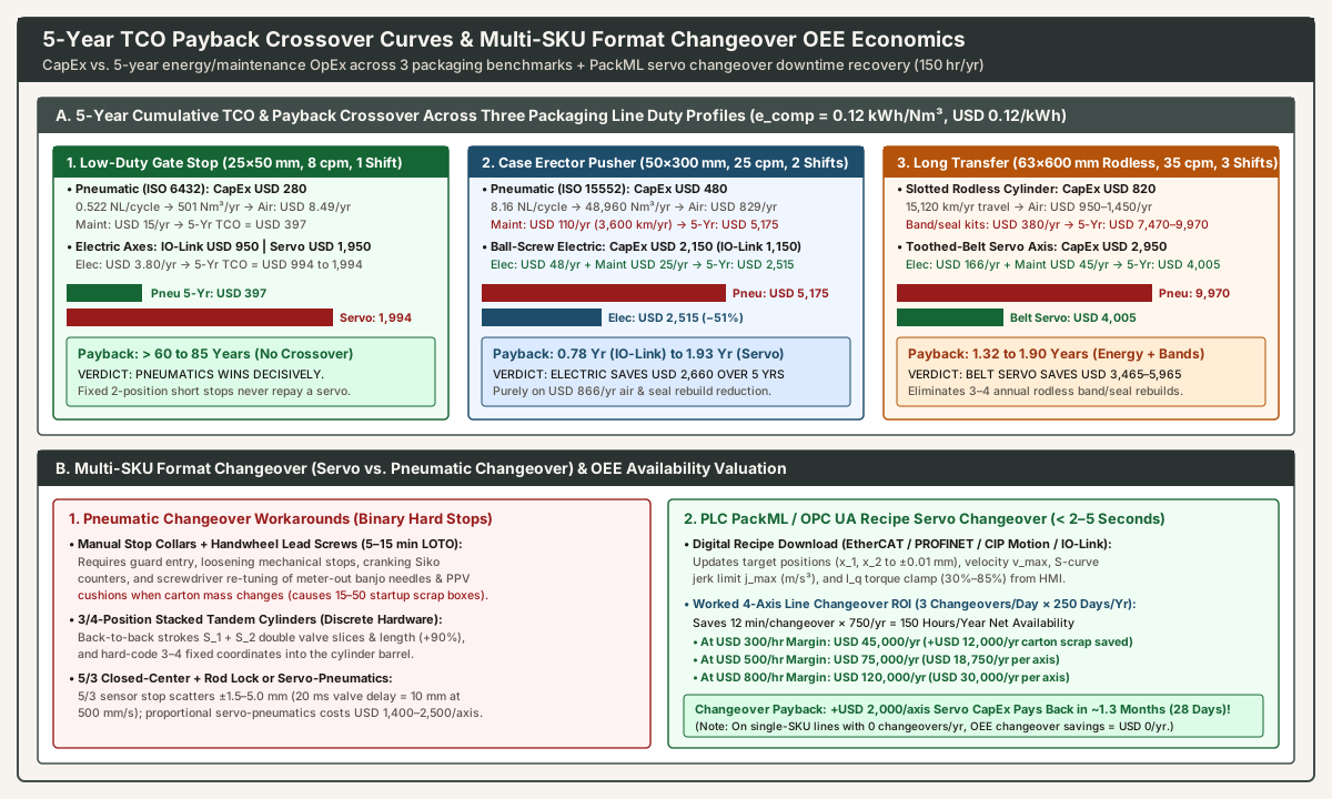
Complete Bill-of-Materials (BOM) CapEx Tiers (USD per Axis)
When comparing initial hardware cost, engineers must include every subcomponent required from the PLC backplane and air header to the moving payload carriage:
Bill-of-Materials (BOM) Component |
Tier 1A: Standard Rodded Pneumatic (ISO 6432 / ISO 15552, 25–50 mm) |
Tier 1B: Slotted or Magnetic Rodless Pneumatic Cylinder (40–63 mm) |
Tier 2: Simplified IO-Link Electric Cylinder (24–48 VDC Stepper/BLDC) |
Tier 3: Full Industrial Servo Linear Axis (400/480 VAC Ball-Screw or Belt) |
|---|---|---|---|---|
| 1. Linear Actuator Body & Guide | USD 85 to 260 (profile cylinder + MF1/MS1/MP2 mount) |
USD 360 to 620 (extruded slotted or 316L magnetic barrel + carriage) |
USD 550 to 980 (ball-screw or belt actuator with integrated motor/encoder) |
USD 750 to 1,800 (precision ball-screw or toothed-belt axis + linear rail) |
| 2. Motor & Holding Brake | Included in pneumatic piston/rod assembly | Included in rodless piston/yoke assembly | Integrated onboard 24/48 VDC closed-loop stepper or BLDC motor |
USD 450 to 950 (400/480 VAC PMSM + multi-turn absolute encoder + brake) |
| 3. Valve Slice or Drive Amplifier | USD 85 to 175 (single 5/2 solenoid slice on fieldbus valve island) |
USD 95 to 190 (5/2 valve slice + optional 3 bar return pressure regulator) |
Integrated onboard IO-Link / digital DI/DO controller + USD 60 port share |
USD 500 to 1,100 (EtherCAT / PROFINET IRT / CIP Motion servo drive) |
| 4. Sensors, Tubing, & Cabling | USD 75 to 150 (2× T-slot magnetic sensors + 2× meter-out banjos + PU tube) |
USD 75 to 150 (2× sensors + 2× flow controls + external hydraulic shocks) |
USD 120 to 220 (M12 24 VDC power + IO-Link communication cordsets) |
USD 100 to 350 (shielded hybrid motor/encoder cable + PLC motion license) |
| 5. Pro-Rata Utility Supply Share | USD 25 to 65 (machine drop-leg FRL unit + safety dump valve share) |
USD 35 to 75 (high-flow FRL unit + soft-start dump valve share) |
USD 120 to 240 (24/48 VDC switched-mode cabinet power supply share) |
Included in cabinet 400/480 VAC mains filter & common DC-bus supply |
Total Installed Axis CapEx (USD) |
USD 250 to 650 (USD 420 typical 32–50 mm baseline) |
USD 550 to 950 (USD 820 typical 50–63 mm shuttle) |
USD 850 to 1,500 (~2.2× to 3.5× rodded pneumatic CapEx) |
USD 1,800 to 4,200 (USD 2,150–3,100 typical; 4×–7× pneumatic CapEx) |
Governing 5-Year TCO, ISO 8778 Air Cost, and Electric Energy Equations
Using the ISO 8778 Standard Reference Atmosphere (ANR: 1.013 bar(a), 20 °C) free-air equation derived on our double-acting pneumatic cylinder sizing guide and the rotary screw compressor benchmark from our compressed air leak detection guide:
- Pneumatic Double-Stroke Free-Air Consumption (
V_cycle_NLin Normal Liters/cycle):V_cycle_NL = [ ((A_cap + A_annular) × S_cm + 2 × A_tube × L_tube_cm) / 1000 ] × ((P_bar + 1.013) / 1.013)whereA_cap = π × D² / 4(cm²),A_annular = π × (D² − d²) / 4(cm²; note thatd = 0on a rodless pneumatic cylinder, soA_annular = A_cap),S_cmis stroke incm,A_tube(cm²) andL_tube_cm(cm) are the internal cross-section and length of one polyurethane connecting tube, andr = (P_bar + 1.013) / 1.013 = 6.923atP_bar = 6.0 bar(g). - Annual Pneumatic Compressed Air Energy Cost (
C_air_yrinUSD/yr):C_air_yr = V_cycle_NL × 60 × cpm × H_yr × (e_comp / 1000) × Rate_kWh × [ 1 / (1 − L_leak) ]wherecpmis cycle rate (cycles/min),H_yris annual operating hours (2,000 hr/yrfor 1 shift;4,000 hr/yrfor 2 shifts;6,000 hr/yrfor 3 shifts),1 Nm³ = 1,000 NL = 35.315 SCF,e_comp = 0.12 kWh/Nm³(~19 kW / 100 SCFMrotary screw compressor + refrigerated dryer),Rate_kWh = USD 0.12/kWh, andL_leak = 0.15(15%plant air leak overhead factor). - Annual Electric Linear Actuator Energy Cost (
C_elec_yrinUSD/yr):C_elec_yr = [ ((2 × F_avg_N × S_m / η_servo) × 60 × cpm × H_yr) / 3,600,000 + (P_standby_W × H_yr / 1000) ] × Rate_kWhwhereE_mech_cycle = 2 × F_avg_N × S_mis round-trip mechanical work in Joules (N·m),η_servo = 0.75(75%wall-to-shaft efficiency),3,600,000 J = 1 kWh, andP_standby_W = 12 to 15 W(24 VDCdrive logic and holding brake standby power). - 5-Year Cumulative TCO (
TCO_5yr) and Simple Payback Period (T_payback):TCO_5yr = CapEx_initial + 5 × (C_energy_yr + C_maint_yr + C_changeover_OEE_yr + C_scrap_yr)T_payback (years) = (CapEx_elec − CapEx_pneu) / [ (C_air_yr − C_elec_yr) + ΔC_maint_yr + ΔC_changeover_OEE_yr + ΔC_scrap_yr ]
The D² × S × cpm × H_yr Scaling Law: Why Duty Cycle Separates Winners from Losers
Notice in the V_cycle_NL and C_air_yr equations that annual compressed air cost scales linearly with stroke S, linearly with cycle rate cpm, linearly with shift hours H_yr, and with the square of cylinder bore diameter (D²):
- Doubling cylinder bore
Dfrom25 mmto50 mmquadruples piston area (4×air per unit stroke). - Increasing stroke
Sfrom50 mm(5 cm) to300 mm(30 cm) multiplies swept volume by6×. - Stepping from a 1-shift low-speed stop (
8 cpm × 2,000 hr/yr = 960,000 cycles/yr) to a 3-shift high-speed transfer shuttle (35 cpm × 6,000 hr/yr = 12,600,000 cycles/yr) multiplies annual cycles by13.125×.
Together, a large-bore, long-stroke, 3-shift pneumatic transfer shuttle consumes 90× to 180× more compressed air per year than a small-bore, short-stroke, 1-shift gate stop—explaining why pneumatic vs electric actuator TCO has a sharp mathematical crossover boundary. As a practical rule of thumb, any fixed-stroke pneumatic cylinder consuming less than 1,500 Nm³/yr (~USD 25/yr in electricity) favors pneumatics on 5-year TCO, whereas any continuous 2- or 3-shift axis consuming more than 35,000 Nm³/yr (~USD 600+/yr) favors an electric linear actuator.
Three Worked Packaging Station 5-Year TCO Benchmarks (Zero-Changeover Energy & Maintenance Baseline)
To isolate pure energy and mechanical maintenance economics before adding multi-SKU changeover downtime (Section 3), let us evaluate three representative packaging stations at P_bar = 6.0 bar(g) (r = 6.923), e_comp = 0.12 kWh/Nm³, L_leak = 15%, and Rate_kWh = USD 0.12/kWh (effective air utility cost = USD 0.01694 per Nm³):
Benchmark 1: Low-Duty Short-Stroke Lane Stop / Carton Flap Clamp (D = 25 mm × S = 50 mm, 8 cpm, 1 Shift = 2,000 hr/yr)
- Pneumatic Inputs & Math (
ISO 6432,D = 25 mm,d = 10 mm):A_cap = 4.91 cm²,A_annular = 4.12 cm²(A_sum = 9.03 cm²),S = 5.0 cm, connected viaL_tube = 120 cm(1.2 m) of6×4 mmPU tubing (A_tube = 0.126 cm²).V_cycle_NL = [ (9.03 × 5.0 + 2 × 0.126 × 120) / 1000 ] × 6.923 = [ (45.15 + 30.24) / 1000 ] × 6.923 = 0.522 NL/cycle.- Annual cycles =
8 × 60 × 2,000 = 960,000 cycles/yr(96 km/yrpiston travel—well below the5,000 kmseal life). - Annual free air =
960,000 × 0.522 / 1000 = 501.1 Nm³/yr(850 kWh/yrcompressor electricity including15%leaks). - Pneumatic Costs:
CapEx = USD 280,C_air_yr = USD 8.49/yr,C_maint_yr = USD 15/yr→ 5-Year TCO =USD 397.
- Electric Inputs & Math (
IO-Link Stepper USD 950orFull Servo USD 1,950):- Round-trip work
E_mech = 2 × (80 N × 0.05 m) = 8.0 J/cycle→2.84 kWh/yrmotion +24 kWh/yr(12 Wstandby) =26.8 kWh/yr→C_elec_yr = USD 3.22 to 3.80/yr,C_maint_yr = USD 5/yr. - Electric 5-Year TCO:
USD 994(IO-Link) orUSD 1,994(Full Servo).
- Round-trip work
- Payback & Verdict: Annual OpEx savings are only
USD 14.69/yr. Simple payback is45.6 years(IO-Link) to113.7 years(Full Servo) (> 60 yearseven if run across 2 shifts). Pneumatics wins decisively. As our parent note (pneumatic vs. servo motion) states, putting a servo on a short 2-position hard stop wastes a drive.
Benchmark 2: Medium-Duty Case Erector Pusher (D = 50 mm × S = 300 mm, 25 cpm, 2 Shifts = 4,000 hr/yr)
- Pneumatic Inputs & Math (
ISO 15552,D = 50 mm,d = 20 mm):A_cap = 19.63 cm²,A_annular = 16.49 cm²(A_sum = 36.12 cm²),S = 30.0 cm, connected viaL_tube = 200 cm(2.0 m) of8×5.5 mmPU tubing (A_tube = 0.238 cm²).V_cycle_NL = [ (36.12 × 30.0 + 2 × 0.238 × 200) / 1000 ] × 6.923 = [ (1,083.6 + 95.2) / 1000 ] × 6.923 = 8.16 NL/cycle.- Annual cycles =
25 × 60 × 4,000 = 6,000,000 cycles/yr(3,600 km/yrlinear piston travel—requiring~1seal and cushion rebuild every14 monthsatUSD 110/yrannualized parts and labor). - Annual free air =
6,000,000 × 8.16 / 1000 = 48,960 Nm³/yr(204 NL/min/7.20 SCFMcontinuous average;6,912 kWh/yrcompressor input). - Pneumatic Costs:
CapEx = USD 480,C_air_yr = USD 829/yr,C_maint_yr = USD 110/yr(USD 939/yrtotal OpEx) → 5-Year TCO =USD 5,175.
- Electric Inputs & Math (
Ball-Screw Servo USD 2,150orIO-Link Screw Axis USD 1,150):- Round-trip work
E_mech = 2 × (350 N × 0.30 m) = 210 J/cycleatη_servo = 0.75→466.7 kWh/yrmotion +48 kWh/yrstandby (less~115 kWh/yrDC-bus regen / unloaded return savings =398 kWh/yr) →C_elec_yr = USD 48/yr,C_maint_yr = USD 25/yr(annual ball-nut re-greasing;73 USD/yrtotal OpEx). - Electric 5-Year TCO:
USD 2,515(Full Servo) orUSD 1,515(IO-Link).
- Round-trip work
- Payback & Verdict: Annual OpEx savings equal
USD 939 − USD 73 = USD 866/yr. Simple payback isT_payback = USD 1,670 / USD 866/yr = 1.93 years(23.1 months) for a full servo axis—and0.78 years(9.3 months) for a simplifiedIO-Linkelectric cylinder, savingUSD 2,660 to 3,660over 5 years before counting any changeover benefits.
Benchmark 3: High-Duty Long-Stroke Transfer Shuttle (Rodless Pneumatic Cylinder D = 50–63 mm × S = 600 mm vs. Toothed-Belt Servo, 35 cpm, 3 Shifts = 6,000 hr/yr)
- Pneumatic Inputs & Math (
Slotted Rodless Cylinder,d = 0,D = 50 to 63 mm):- For a
63 mmbore (2 × A_cap = 62.34 cm², or39.27 cm²for50 mmbore),S = 60.0 cm,2.5 mof10×7 mmtubing (A_tube = 0.385 cm²): full-pressureV_cycle_NL = 17.7 to 27.2 NL/cycle, or11.5 to 17.0 NL/cyclewhen optimized with a3.0 barcheck-regulator on the unloaded return stroke. - Annual cycles =
35 × 60 × 6,000 = 12,600,000 cycles/yr(15,120 km/yrcarriage travel!). Because slotted rodless pneumatic cylinder inner/outer sealing bands and piston seals wear out every3,000 to 5,000 km, a 3-shift shuttle requires3 to 4band and seal rebuilds per year (C_maint_yr = USD 380/yrin seal kits and planned maintenance labor). - Annual free air =
56,000 to 85,600 Nm³/yr(with return-pressure reduction) or135,000 Nm³/yr(unregulated6 barboth ways) →C_air_yr = USD 950 to 1,450/yr(up toUSD 2,285/yrunregulated). - Pneumatic Costs:
CapEx = USD 820,OpEx = USD 1,330 to 1,830/yr→ 5-Year TCO =USD 7,470 to 9,970.
- For a
- Electric Inputs & Math (
Toothed-Belt Servo Linear Axis,CapEx = USD 2,950):- Round-trip work
E_mech = 2 × (400 N × 0.60 m) = 480 J/cycleatη_belt_servo = 0.78→1,292 kWh/yr+90 kWh/yrstandby =1,382 kWh/yr→C_elec_yr = USD 166/yr,C_maint_yr = USD 45/yr(rail lubrication and belt tension check; belt life15,000 to 30,000+ km). - Electric 5-Year TCO:
USD 4,005.
- Round-trip work
- Payback & Verdict: Annual OpEx savings equal
USD 1,119 to 1,619/yr(orUSD 2,454/yragainst an unregulated63 mmcylinder). TheUSD 2,130CapEx delta pays back in1.32 to 1.90 years(0.87 yearsvs. unregulated) purely on compressed air and rodless band rebuilds, deliveringUSD 3,465 to 5,965net 5-year TCO savings.
| Cost & Performance Metric | Benchmark 1: Low-Duty Gate (25×50 mm, 8 cpm, 1 Shift) |
Benchmark 2: Medium-Duty Pusher (50×300 mm, 25 cpm, 2 Shifts) |
Benchmark 3: High-Duty Shuttle (63×600 mm Rodless, 35 cpm, 3 Shifts) |
|---|---|---|---|
Annual Cycles & Travel (km/yr) |
960,000 cycles/yr (96 km/yr) |
6,000,000 cycles/yr (3,600 km/yr) |
12,600,000 cycles/yr (15,120 km/yr) |
Pneumatic ISO 8778 Air (NL/cycle & Nm³/yr) |
0.522 NL/cycle (501 Nm³/yr) |
8.16 NL/cycle (48,960 Nm³/yr) |
11.5–17.0 NL/cycle opt. (56,000–85,600 Nm³/yr) |
| Pneumatic CapEx / Annual Energy / Annual Maint | USD 280 / USD 8.49/yr / USD 15/yr |
USD 480 / USD 829/yr / USD 110/yr |
USD 820 / USD 950–1,450/yr / USD 380/yr |
| Electric CapEx / Annual Energy / Annual Maint | USD 950–1,950 / USD 3.80/yr / USD 5/yr |
USD 1,150–2,150 / USD 48/yr / USD 25/yr |
USD 2,950 (Belt) / USD 166/yr / USD 45/yr |
5-Year Cumulative TCO (Pneumatic vs. Electric) |
USD 397 (Pneu) vs. USD 994–1,994 (Elec) |
USD 5,175 (Pneu) vs. USD 1,515–2,515 (Elec) |
USD 7,470–9,970 (Pneu) vs. USD 4,005 (Elec) |
Simple Energy + Maint Payback (T_payback) |
> 45 to 113 Years (Pneumatics Wins) |
0.78 Yr (IO-Link) / 1.93 Yr (Servo) |
1.32 to 1.90 Years (Electric Belt Wins) |
3. Multi-SKU Packaging Format Changeover (Servo vs. Pneumatic Changeover) and OEE Downtime Valuation
While Section 2 evaluated fixed-stroke stations, modern contract packagers, food and beverage bottlers, and e-commerce fulfillment lines routinely run 3 to 12 distinct product SKUs on the same secondary packaging line, switching carton lengths, case widths, tray heights, and pack patterns 1 to 6 times per day. Whenever a station’s target stop coordinate or velocity profile must change between product runs, servo vs pneumatic changeover economics completely dominate the TCO equation.
Why Standard Pneumatics Is a Binary 2-Position Device (and the Four Multi-Position Workarounds)
As established on our parent page (when a packaging motion is air, and when it is a servo), a standard double-acting pneumatic cylinder has no internal position feedback encoder and is driven by a compressible fluid (air bulk modulus β_air = γ × P_abs ≈ 9.8 bar at 6.0 bar(g), roughly 1,500× more compliant than hydraulic oil). Once the 5/2 valve opens, the piston accelerates until it physically bottoms out against the rear cap head, front rod head, or an external rigid stop block.
When machine builders attempt to adapt pneumatic cylinders to multi-SKU format changeovers, they must choose among four mechanical or electro-pneumatic workarounds—each carrying severe operational penalties:
- Manual Stop Collars, Handwheel Lead Screws, and Mechanical Counters (
5 to 15 MinutesLOTO Downtime): Technicians execute Lockout/Tagout (LOTO), open interlocked safety doors, loosen clamp levers on slotted stop blocks or crank manual positioning screws while reading a digital mechanical counter (Sikoindicator), and re-lock across4 to 20adjustment points. Worse, when switching from a heavy12 kgglass-bottle case to a light2.5 kgaluminum-can tray, the pneumatic cylinder’s terminal velocity and end-of-stroke kinetic energy (E_k = 0.5 × m × v²) shift dramatically. Operators must use a flathead screwdriver to re-tune the cylinder-portmeter-outbanjo flow control needles (pneumatic flow control valve sizing) andPPVcushion screws by trial and error—losing10 to 35 minutesof line availability per changeover plus15 to 50crushed or mis-erected startup cartons. - Stacked Tandem (
3-Positionor4-Position) Multi-Stroke Cylinders: Bolting twoISO 15552cylinders back-to-back with independent strokesS_1andS_2(or specifying a 3-position stop cylinder with an intermediate stop flange) provides3or4discrete mechanical stop coordinates (0,S_1,S_2, andS_1 + S_2), actuated by two5/2solenoid valves. However, tandem cylinders increase overall housing length by80% to 110%, double valve manifold slices, tubing runs, and reed sensors, and hard-code the exact SKU dimensions into the machined aluminum barrel. If marketing introduces a new promotional carton next quarter whose width differs by18 mm, the tandem cylinder cannot position to that coordinate without machined mechanical shims or cylinder replacement. - Mid-Stroke
5/3Closed-Center Valve + Pneumatic Rod Lock Triggered by Magnetic Sensor: Commanding a5/3closed-center valve to block both ports when a T-slot Hall sensor detects the passing piston magnet—even when reinforced by a spring-applied pneumatic friction rod lock—produces±1.5 to ±5.0 mmstopping scatter. Because a solenoid pilot valve and mechanical rod lock cartridge require12 to 30 msof response time (at v = 500 mm/s, 20 ms equals 10.0 mm of piston coasting!), any variation in header pressureP_1,meter-outbackpressureP_2, or seal lubrication shifts the actual stopping point. - Closed-Loop Servo-Pneumatics (
5/3Proportional Flow Valve + Linear Magnetostrictive Encoder): Pairing a cylinder with a high-bandwidth5/3proportional directional control valve (100 to 250 Hz), a continuous0–10 VorSSIlinear displacement transducer, and a dedicated pressure/position PID controller achieves±0.2 to ±0.5 mmmid-stroke positioning. However, a servo-pneumatic axis costsUSD 1,400 to 2,500+per axis—eliminating the CapEx advantage of pneumatics while retaining8%–18%compressed air energy efficiency, continuous proportional spool leakage (0.1 to 0.4 SCFMintentional bleed noted on our leakage survey plan), and breakaway stick-slip sensitivity (µ_s > µ_k).
| Changeover Architecture | Programmable Stop Coordinates | Mid-Stroke Repeatability | Changeover Time per Axis (LOTO + Tuning) |
Force & Speed Profile Adaptation | Hardware CapEx (USD/axis) |
Primary Packaging Line Limitation |
|---|---|---|---|---|---|---|
Standard 2-Position Cylinder + Manual Stop Collar |
2 (manual wrench move for SKU #2) |
±0.10 mm (against rigid stop block) |
5 to 15 min (manual LOTO + meter-out screwdriver tuning) |
Fixed F = P × A; manual needle speed adjustment |
USD 280–650 |
High changeover downtime (10–35 min/line) and startup carton scrap |
Stacked Tandem 3/4-Position Cylinder |
3 or 4 fixed (0, S_1, S_2, S_1+S_2) |
±0.10 mm (internal mechanical stops) |
< 2 s (among the 3–4 hard-coded stops only) |
Fixed F = P × A unless dual regulators added |
USD 550–1,100 |
+90% length; cannot accommodate a 5th SKU or 10 mm box resize |
5/3 Closed-Center Valve + Rod Lock + Sensor |
1 to 3 sensor-switched zones |
±1.5 to ±5.0 mm (coasting scatter) |
3 to 8 min (sliding T-slot reed switches by hand) |
Uncontrolled deceleration; air-spring bounce | USD 500–900 |
12–30 ms valve/brake response delay causes speed-dependent overshoot |
| Closed-Loop Servo-Pneumatic Axis | Infinite (analog / SSI transducer) |
±0.20 to ±0.50 mm |
< 3 s (PLC recipe target update) |
PID pressure modulation; sensitive to seal stiction | USD 1,400–2,500+ |
Costs as much as an electric servo while wasting compressed air |
Simplified IO-Link Electric Cylinder |
2 to 32+ recipe (or dynamic IO-Link mm) |
±0.02 to ±0.05 mm |
< 2 to 5 s (zero guard entry) |
Programmable cruise speed & current thrust limit | USD 850–1,500 |
Speed capped around 0.3–0.8 m/s; no multi-axis camming |
Full Industrial Servo Axis (Ball-Screw / Belt) |
Infinite (16–24 bit absolute encoder) |
±0.005 to ±0.10 mm |
< 1 to 3 s (PackML recipe download) |
Full S-curve jerk j_max + real-time I_q torque clamp |
USD 1,800–4,200 |
Higher initial CapEx; requires cabinet drive or decentralized bus |
PLC Recipe-Driven Changeover (ISA-TR88.00.02 PackML / OPC UA) and S-Curve Jerk Control
On an electric servo axis (EtherCAT, PROFINET IRT, CIP Motion) or simplified IO-Link stepper actuator, every SKU format parameter resides in the PLC’s ISA-TR88.00.02 (PackML) recipe data block:
- Zero-Touch Multi-Axis Coordinate Download (
< 2 to 5 Seconds): When the operator scans a new work-order barcode at the HMI and transitions the machine state toPackML Resetting / Changeover, the PLC writes target absolute coordinates (x_extend, x_retract, x_intermediateto0.01 mm), cruise velocities (v_max), acceleration/deceleration ramps (a_acc, a_dec), and torque limits across10 to 40axes simultaneously. Every guide rail, case magazine stop, glue flap folder, and transfer pusher moves to its exact verified coordinate in< 2 to 5 secondswithout opening a guard door or touching a hand tool. - S-Curve Jerk Limiting (
j_max = da/dtinm/s³): Unlike a pneumatic cylinder that applies a step-function pressure force at breakaway and decelerates abruptly over the last17 to 32 mmofPPVcushion spear travel, a servo controller shapes a continuous 7-segment S-curve velocity profile (bounded jerk j_max). Eliminating acceleration discontinuities prevents liquid sloshing in open-top fill trays, stops tall thin-wall PET bottles from tipping on lane diverters, and eliminates end-of-stroke frame vibration. - Closed-Loop
I_qTorque and Force Clamping (Soft TouchCorrugated Handling): When switching from heavy double-wall export shipping cases (BC-flute) to ultra-light recycled retail-ready trays (E-flute), the PLC recipe automatically lowers the servo drive’s bipolar torque limit (P-0-0092/OD 0x6072) from85%to30%of rated thrust—preventing crushed carton flutes on the very first box without requiring a technician to dial down a manualISO 6953pressure regulator.
Worked OEE Changeover Downtime & Scrap Valuation Model (USD/yr)
To quantify servo vs pneumatic changeover return on investment, compute the annual value of recovered Overall Equipment Effectiveness (OEE = Availability × Performance × Quality) availability hours and eliminated post-changeover startup scrap:
ΔC_changeover_OEE_yr (USD/yr) = [ (t_manual_min − t_servo_min) / 60 ] × N_changeovers_day × Days_yr × Margin_USD_hr + (ΔN_scrap_boxes × Cost_box × N_changeovers_day × Days_yr)
Consider a secondary case-packing line operating 250 days/year with 3 SKU changeovers per day (750 changeovers/year), where replacing 4 manual-stop pneumatic axes (case width stop, lug pusher stroke, flap tucker, and lane divider) with 4 electric servo or IO-Link actuators (total CapEx delta = 4 × USD 2,000 = +USD 8,000, or +USD 2,000 per axis) eliminates 12 minutes (0.20 hr) of LOTO wrenching and meter-out needle tuning per changeover, plus 20 crushed startup cartons (USD 0.80 each = USD 16.00 scrap per changeover):
- Recovered Annual Production Time:
(12 min / 60) × 3 changeovers/day × 250 days/yr = 150.0 hours/yearof additional net running availability. - Annual OEE Availability Value Across Three Line Contribution Margins:
- Conservative Co-Packing Line (
USD 300/hrcontribution margin):150 hr/yr × USD 300/hr = USD 45,000/yr(USD 11,250/yrper axis). - Standard Food & CPG Line (
USD 500/hrcontribution margin):150 hr/yr × USD 500/hr = USD 75,000/yr(USD 18,750/yrper axis). - High-Speed Beverage / Pharma Line (
USD 800/hrcontribution margin):150 hr/yr × USD 800/hr = USD 120,000/yr(USD 30,000/yrper axis).
- Conservative Co-Packing Line (
- Annual Startup Carton Scrap Savings:
750 changeovers/yr × 20 cartons × USD 0.80 = USD 12,000/yr(USD 3,000/yrper axis). - Payback Period: Even at the conservative
USD 300/hrline margin (USD 45,000/yr OEE + USD 12,000/yr scrap = USD 57,000/yracross the 4 axes, orUSD 14,250/yrper axis), the+USD 8,000(+USD 2,000/axis) electric hardware premium pays back in0.14 years(1.68 months/35 operating days)—and in0.09 years(~1.1 months/23 operating days) atUSD 500/hr! - The Single-SKU Counter-Rule: Conversely, on a dedicated single-SKU line running the exact same container size 365 days a year (
N_changeovers_day = 0), changeover OEE savings equalUSD 0/yr, and actuator selection reverts strictly to the duty-cycle energy and maintenance equations in Section 2.
4. Long-Stroke Linear Mechanics: Rodless Pneumatic Cylinder vs. Toothed-Belt and Ball-Screw Electric Axes
When a packaging transfer shuttle, case layer pusher, or gantry axis requires a stroke longer than 500 to 760 mm (20 to 30 in.), standard rodded cylinders (ISO 15552) encounter two physical barriers documented on our double-acting pneumatic cylinder sizing guide: (1) Euler column buckling (F_crit = π² × E × I / (K × L)²) of the extended piston rod, and (2) an overall machine footprint exceeding 2 × Stroke + dead length. To eliminate the protruding rod, engineers choose between a rodless pneumatic cylinder (slotted or magnetically coupled) and an enclosed rodless electric linear actuator (toothed-belt or ISO 3408 ball/roller screw).
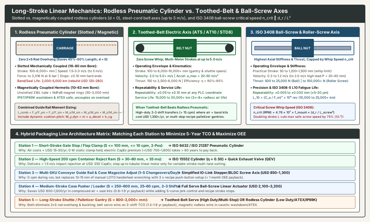
Four-Way Long-Stroke Mechanical Comparison Matrix
Drawing on Pneumatic Tips: How do pneumatic rodless cylinders, slides work?, Power & Motion: Right-Sizing Rodless Pneumatic Actuators, and Linear Motion Tips: Linear actuators: Pneumatic or electric?, the table below compares all four enclosed long-stroke architectures head-to-head:
| Engineering Parameter | 1. Slotted Mechanically Coupled Rodless Pneumatic Cylinder |
2. Magnetically Coupled Hermetic Rodless Pneumatic Cylinder |
3. Electric Toothed-Belt Linear Actuator (AT5 / AT10 / STD8) |
4. Electric Ball-Screw (ISO 3408) or Roller-Screw Actuator |
|---|---|---|---|---|
| Internal Coupling & Sealing Mechanism | Metal yoke links internal piston to external carriage through a longitudinal barrel slot sealed by an inner stainless/PU pressure band + outer dust strip | Unslotted thin-wall 304/316L stainless tube; rare-earth (NdFeB) magnet rings couple piston to external carriage across the tube wall |
Steel-cord or aramid-cord polyurethane toothed belt driven by precision timing pulleys; carriage rides on internal recirculating ball rail | Rotating alloy-steel ball screw (ISO 3408) or planetary roller screw with preloaded nut; carriage guided by internal linear rail |
Practical Stroke Range (S) |
100 to 6,000+ mm (saves 45%–50% install length vs. rodded cylinder; zero buckling) |
50 to 2,500–3,000 mm |
100 to 6,000–10,000+ mm (zero screw whip; supports multi-meter gantry spans) |
50 to 1,200–1,500 mm (up to 2,500–3,000 mm only with rotating nut or screw supports due to whip n_crit) |
Max Linear Velocity (v_max) & Accel (a_max) |
1.5 to 3.0 m/s standard (up to 5.0 m/s high-speed); a_max = 15–30 m/s² (needs external hydraulic shocks > 1.0 m/s) |
0.2 to 1.2 m/s (excessive inertia F = m × a uncouples the magnetic ring!) |
2.0 to 5.0+ m/s (highest controlled velocity); a_max = 20–50 m/s² with S-curve |
0.3 to 1.2 m/s (up to 1.5–2.0 m/s with high lead P_lead = 20–40 mm); a_max = 10–20 m/s² |
Continuous Axial Thrust Force (F_max) |
120 N (16 mm bore) to 3,016 N (80 mm bore at 6 bar); 100% symmetrical (d = 0) |
50 N (10 mm bore) to 1,100–1,600 N (63 mm bore, capped by magnetic breakaway force) |
150 N to 3,500–6,000 N (limited by belt tooth shear and tensile cord rating) |
500 N to 25,000 N (ball screw) and up to 100,000+ N (planetary roller screw) |
| Positional Repeatability & Mid-Stroke Stops | ±0.10 mm at 2 fixed end stops only (±0.2–0.5 mm mid-stroke only with costly servo-pneumatics) |
±0.15 mm at 2 fixed end stops only (magnetic flux + air spring prevents stiff mid stops) |
±0.05 to ±0.10 mm at any PLC coordinate (elastic belt stretch ΔL = F × L / (E × A) under load) |
±0.005 to ±0.030 mm (±5–30 µm) at any coordinate (highest axial stiffness k_axial) |
Service Life (km) & Maintenance |
2,000 to 5,000 km (~1.5–4M cycles at 600 mm) before inner/outer sealing bands & U-cups need replacement (USD 120–280 kit) |
3,000 to 6,000 km (internal PTFE/acetal wear rings; zero slot band replacement) |
15,000 to 30,000+ km (3×–8× rodless pneumatic life; tension check & rail grease every 5,000–10,000 km) |
10,000 to 25,000+ km (ISO 3408-5 L_10 fatigue life; re-grease ball nut every 2,500–5,000 km or 1 yr) |
Washdown (IP69K) & Explosion (ATEX) Rating |
Fair (IP40 at slot): Slot ingests corrugated dust, sugar powder, or caustic spray unless purged or stainless-banded |
Excellent (IP67 / IP69K & ATEX Ready): Hermetically sealed 316L tube with zero slot and zero spark hazard |
Moderate (IP40–IP54): Extrusion slot requires stainless cover strip or sealed enclosure in wet zones |
Good to Excellent (IP65–IP69K): Sealed 316L rod-style electric cylinders match washdown ratings (ATEX motor adds CapEx) |
Governing Equations: Ball-Screw Critical Whip Speed (n_crit), ISO 3408-5 L_10 Fatigue Life, and Combined Guide Moments
Three mechanical equations govern long-stroke actuator selection between a rodless pneumatic cylinder, a toothed-belt electric axis, and a ball-screw electric axis:
ISO 3408Ball-Screw Critical Whip Speed (n_crit ∝ d_r / L_screw²): Why cannot a standard ball-screw electric actuator match the3.0 to 5.0 m/sspeed and3,000+ mmstroke of a slotted rodless pneumatic cylinder or toothed-belt electric axis? As a threaded steel screw shaft of root diameterd_r(mm) and unsupported free lengthL_screw(mm) spins at high RPM, centrifugal runout excites its first lateral bending natural frequency (critical whip speedn_crit):n_crit (RPM) = 4.76 × 10^7 × f_mount × (d_r / L_screw²)andv_max,allow (mm/s) = (0.80 × n_crit / 60) × P_lead_mmwheref_mountis the end-bearing support factor (f_mount = 0.36for fixed-free,1.00for simple-simple,1.47for fixed-simple, and2.23for fixed-fixed angular-contact bearings), and safe operating speed is capped at80%ofn_crit.- Worked Whip Limit Check: Consider a
Ø20 mmball screw (root diameter d_r = 16.5 mm, high leadP_lead = 20 mm/rev, fixed-simple bearingsf_mount = 1.47):- At
L_screw = 600 mmstroke:n_crit = 4.76 × 10^7 × 1.47 × (16.5 / 600²) = 3,207 RPM→n_allow = 2,566 RPM→v_max,allow = 855 mm/s(0.86 m/s). - Doubling stroke to
L_screw = 1,200 mm: Becausen_critdrops with1 / L_screw², critical speed plummets by75%(4×reduction) ton_crit = 802 RPM(n_allow = 641 RPM), capping linear velocity atv_max,allow = 214 mm/s(0.21 m/s)! - Design Rule: Whenever a packaging transfer requires strokes
> 1,000 to 1,200 mmcombined with velocities> 1.0 to 1.5 m/s, replace the rotating ball-screw shaft with either a toothed-belt electric linear axis (for high-duty 2/3-shift or multi-stop servo motion) or a rodless pneumatic cylinder (for low-duty 2-position end-to-end motion).
- At
- Worked Whip Limit Check: Consider a
ISO 3408-5Rolling-Contact Fatigue Life (L_10) for Ball Screws vs. Planetary Roller Screws: The nominal fatigue lifeL_10(in revolutions, achieved by90%of identical screw assemblies before subsurface spalling) under cubic mean axial forceF_m(N) and catalog dynamic load ratingC_a(N) is:L_10 (revs) = (C_a / F_m)^3 × 10^6andL_10 (km) = (L_10 / 10^6) × P_lead_mm = (C_a / F_m)^3 × P_lead_mmAs explained in Linear Motion Tips: How roller screw and ball screw actuators compare in high-force applications, planetary roller screws transfer load across dozens of threaded line-contact rollers rather than point-contact steel balls, providing2× to 3×higherC_ain the same envelope—which cubes (2³ = 8×to3³ = 27×) to deliver8× to 27×longerL_10fatigue life on high-force pressing, clinching, and thermoforming stations.- Combined Guide-Rail Moment Load Fraction (
L_combined <= 1.0) on Rodless & Belt Carriages: Whether sizing a rodless pneumatic cylinder (Power & Motion: Right-Sizing Rodless Pneumatic Actuators) or an electric belt/screw carriage carrying an eccentric payload massmat center-of-gravity offsets(L_x, L_y, L_z), verify that the sum of normal load (F_z), side load (F_y), roll (M_x), pitch (M_y), and yaw (M_z) ratios never exceeds1.0:L_combined = (F_y / F_y,max) + (F_z / F_z,max) + (M_x / M_x,max) + (M_y / M_y,max) + (M_z / M_z,max) <= 1.0On pneumatic rodless shuttles decelerating abruptly against end-of-stroke cushions (a_decel = 10 to 25 m/s²), dynamic pitch momentM_y,dyn = m × a_decel × h_cgis2× to 4×higher than on an electric belt actuator executing a smooth S-curve deceleration (a_decel = 4 to 8 m/s²), often allowing the electric axis to use a smaller, lighter guide profile.
5. Hybrid Packaging Line Selection Matrix: Station-by-Station Decision Checklist
Our parent guide (when a packaging motion is air, and when it is a servo) states the core rule for packaging machinery design: “Compare the job in front of you. One actuator does not stand in for the other.” Building an ideological “100% all-servo” machine inflates capital cost by tens of thousands of dollars on simple binary gates and clamps, while building a “100% pneumatic” multi-SKU machine bleeds plant profitability through compressor electricity, annual seal rebuilds, and manual LOTO changeover downtime.
Use the station-by-station engineering matrix below—and the expanded 7-question specification worksheet that follows—to assign the optimal drive architecture to each motion axis on a packaging line:
| Packaging Line Station & Motion Task | Typical Stroke (S) & Cycle Rate (cpm) |
Stop Coordinates & Changeover Frequency | Recommended Actuator Architecture | Primary 5-Year TCO & OEE Engineering Justification |
|---|---|---|---|---|
| 1. Safety Gate Lock, Carton Flap Hold-Down, or Binary Lane Stop | S = 15–100 mm, 1–10 cpm (or static dwell) |
2 fixed hard stops (0 SKU changeovers) |
Standard ISO 6432 or ISO 21287 Compact Pneumatic Cylinder (USD 250–450) |
Air costs < USD 10–30/yr; 0 W holding power during static clamping dwells; electric CapEx premium takes > 60 years to pay back. |
2. High-Speed 200 Container/min Inspection Reject Ram |
S = 30–80 mm, intermittent burst (< 30–40 ms stroke) |
2 fixed positions (retracted home vs. reject push) |
ISO 15552 Pneumatic Cylinder (η = 0.50) + Quick Exhaust Valve (QEV) (USD 320–500) |
High force-to-mass ratio and compliant air cushion survive violent container impacts (reject actuator checklist). Upgrade to tubular linear motor only for variable-force multi-lane sorting. |
| 3. Multi-SKU Conveyor Guide Rail, Case Magazine Width, & Glue-Head Adjust | S = 100–500 mm, 0 cpm during run (moves only at setup) |
3 to 20+ SKU recipes (1–6 changeovers/day) |
Simplified IO-Link Electric Stepper/BLDC Screw Actuator (USD 850–1,350 with brake) |
Consumes 0 Nm³/yr of air and eliminates 10–20 min of manual LOTO handwheel cranking per changeover—paying back in < 1 month via OEE availability recovery. |
| 4. Continuous Case Erector Pusher, Carton Loader, or Flighted Elevator | S = 200–600 mm, 20–60 cpm (2–3 shifts) |
2 to 12+ recipe strokes + S-curve velocity profile |
Full Servo ISO 3408 Ball-Screw Linear Actuator (USD 2,100–3,200) |
Saves USD 800–1,600/yr in compressed air and seal kits (0.8–1.9 yr energy payback) while adding ±0.01 mm recipe stops, S-curve anti-tip motion, and I_q crush protection. |
5. Long-Stroke Case Transfer Shuttle or Palletizer Layer Gantry (Dry Zone) |
S = 600–3,000+ mm, 15–40 cpm (2–3 shifts) |
2 to 20+ recipe coordinates (high speed 1.5–4.0 m/s) |
Full Servo Toothed-Belt Linear Actuator (USD 2,600–4,200) |
Eliminates 2 × S rod overhang and ball-screw whip (n_crit); 15,000–30,000 km belt life avoids 3–4 annual rodless seal band rebuilds (1.3–1.9 yr payback). |
6. Long-Stroke Transfer in IP69K Caustic Washdown or ATEX Hazardous Zone |
S = 400–2,500 mm, 2–15 cpm (1–2 shifts) |
2 fixed end-of-stroke hard stops |
Hermetic 316L Magnetically Coupled Rodless Pneumatic Cylinder (USD 750–1,300) |
Unslotted stainless barrel has zero external slot to trap bacteria or powder, zero spark source for ATEX Class I Div 1, and 45%–50% shorter footprint than rodded cylinders. |
Seven-Question Station Specification Worksheet (Expanding Parent Page #7972)
Before releasing a packaging station Bill of Materials or retrofitting a legacy cylinder identified via how to read an old pneumatics part number, complete these seven quantitative checks alongside the four baseline questions on when a packaging motion is air, and when it is a servo:
- Where must the actuator stop, and how many SKU recipes run on this line? If the axis requires
>= 3variable stop coordinates or changes stroke>= 1 time/day, calculateΔC_changeover_OEE_yr; anIO-Linkor servo electric axis almost always pays back in< 1 to 3 months. - What is the annual swept air volume (
D² × S × cpm × H_yr)? ComputeV_cycle_NLincluding2 × A_tube × L_tubepolyurethane tubing dead volume. IfC_air_yr + C_maint_yrexceedsUSD 600 to 900/yr, an electric ball-screw or belt actuator pays back on utility and maintenance savings alone within1 to 2 years. - Does the cycle include a long static high-force clamping dwell (
v = 0)? If yes, either retain a pneumatic cylinder (0 Wstatic hold) or specify a24 VDCspring-applied holding brake / self-locking screw on the electric actuator so stator windings do not overheat at stall (P_copper = 3 × I_hold² × R_phase). - What dynamic force (
F_load / η) or S-curve jerk limit (j_max) does the package require? Useη = 0.70(transfer) orη = 0.50(> 500 mm/shigh speed) when sizing pneumatic bores; specify servo S-curve ramping (j_max) andI_qtorque clamping when handling open liquid trays or thin-flute recycled cartons. - Does the stroke exceed
500 to 760 mm(Euler buckling F_critor2 × Sfootprint limit)? Compare a slotted/magnetic rodless pneumatic cylinder against a toothed-belt orISO 3408ball-screw electric axis, checking ball-screw critical whip speedn_crit ∝ d_r / L_screw²wheneverS > 1,000 mmandv > 1.0 m/s. - What happens if air pressure or electrical power drops (
ISO 13849-1safety state)? Remember Cosford’s rule that compressed air acts like a spring; vertical or overhead loads require a mechanical pneumatic rod lock cartridge (with 5/3 closed or exhausted center) or a spring-set electric servo holding brake. - What are the environmental hygiene (
ISO 8573-1/IP69K) and explosion (ATEX) boundaries? Near open food containers, account forISO 8573-1:2010 [2:2:1]oil-free filtration (air preparation for packaging lines) or switch to sealed electric / magnetic rodless actuators to eliminate exhaust mist in the product zone.