
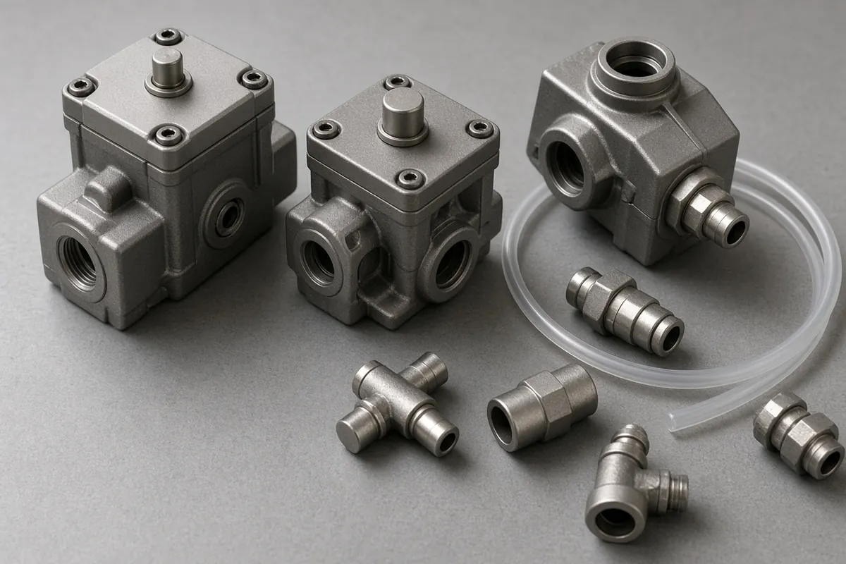
Selecting and tuning a pneumatic flow control valve—often cataloged as a unidirectional throttle-check valve or speed controller cylinder fitting—governs whether a pneumatic actuator moves at a repeatable steady velocity (v_ss) or suffers from 2 to 15 Hz stick-slip chatter, runaway vertical drops, and missed cycle windows. Because compressed air at 6.0 bar(g) has an adiabatic bulk modulus (β_air = γ × P_abs ≈ 9.8 bar) that is roughly 1,500× more compliant than hydraulic fluid (β_oil ≈ 15,000 bar), installing a meter-in valve instead of a meter-out regulator or undersizing its ISO 6358 sonic conductance C causes cylinders to stall mid-stroke, slam aluminum end caps, or waste 25% to 50% of cycle speed repeatability.
In our parent guide on questions to write down before you size a cylinder inside the pneumatics section, Josh Cosford’s vertical-lift worksheet (Pneumatic Tips: A designer’s guide to pneumatic cylinders) deducts 20% to 40% (30% mean, reducing 100 psi shop air to 70 psi effective differential) from static supply pressure specifically because metering out restricts air leaving the opposing cylinder port and builds stabilizing backpressure. While our sibling reference on double-acting pneumatic cylinder force and air consumption uses that 30% to 50% dynamic deduction (η = 0.70 and 0.50) to size ISO 15552 and ISO 6432 cylinder bores, this engineering guide examines the flow control hardware itself: internal parallel needle-and-check construction, ISO 1219-1 symbol orientation, meter out vs meter in pneumatic circuit physics, quantitative ISO 6358 sonic conductance (C and b) orifice sizing, polyurethane (PU) tubing dead-volume compliance penalties, and Quick Exhaust Valves (QEV) for < 30–50 ms packaging reject rams (reject actuator checklist).
| Flow Control Hardware Family & Circuit Role | Throttled Flow Direction | ISO 1219-1 Check Arrow Orientation |
Typical Sonic Conductance C (G1/8–G1/2) |
Pneumatic Stiffness & Velocity Stability | Primary Packaging Line Application |
|---|---|---|---|---|---|
Direct-Port Banjo Meter-Out Speed Controller (Swivel Elbow) |
Exhaust air leaving cylinder work port (Port 2 or Port 4) |
Points toward cylinder port (free flow in, metered flow out) |
1.10 to 9.80 NL/(s·bar) (Q_nN = 300–2,700 NL/min) |
Maximum (100% baseline): Zero unthrottled tubing dead volume between piston and orifice |
Standard on 95%+ of double-acting cylinders: case pushers, vertical lifts, indexing gates |
Direct-Port Banjo Meter-In Speed Controller (Supply Regulator) |
Supply air entering cylinder work port (Port 2 or Port 4) |
Points away from cylinder port (metered flow in, free flow out) |
1.10 to 9.80 NL/(s·bar) (Q_nN = 300–2,700 NL/min) |
Low on double-acting (P_2 ≈ 0 bar): Prone to 2–15 Hz stick-slip below 250 mm/s |
Single-acting spring-return (3/2) cylinders, air bellows, low-friction glass/graphite pressing |
| Inline Tube-to-Tube / Bulkhead Flow Control Valve | Unidirectional (meter-out or meter-in depending on tube orientation) |
Stamped arrow on body indicates free-flow bypass direction | 0.80 to 8.50 NL/(s·bar) (Ø4 to Ø12 mm push-in collets) |
Moderate: Degrades if tubing between inline valve and cylinder exceeds 20–30 cm |
Guarded tooling, reciprocating hot seal jaws, or remote operator sub-panels |
Manifold Exhaust-Port Throttle Muffler (Ports 3 & 5 on 5/2 Valve) |
Bidirectional needle on 5/2 valve exhaust ports (3/R and 5/S) |
Variable restriction symbol only (no parallel check valve required) | 1.50 to 12.0 NL/(s·bar) (G1/8 to G1/2 sintered bronze/PE) |
Lowest (-40% to -60% stiffness): Entire 1–3 m PU tube acts as compliant air spring |
Low-cost, non-critical long-stroke clamps where port access is blocked |
Quick Exhaust Valve (QEV) + Throttled Silencer / ASV Hybrid |
Local atmospheric dump at cylinder port (Port 2 -> Port 3) |
3-port shuttle poppet (seals Port 3 on supply; seals Port 1 on exhaust) |
4.50 to 9.50 NL/(s·bar) in G1/8–G1/4 (2.5×–4× banjo capacity) |
Ultra-fast depressurization: Cuts stroke transit time by 35% to 55% |
High-speed < 30–50 ms container reject rams (200 containers/min bottling lines) |
1. Internal Architecture of a Pneumatic Flow Control Valve and ISO 1219-1 Symbols
In industrial fluid power terminology (Pneumatic Tips: What are Pneumatic Valves?), a pneumatic flow control valve used for cylinder velocity regulation is a unidirectional throttle-check valve (commonly called a speed controller cylinder fitting). Unlike a simple two-way needle valve that restricts flow in both directions, a cylinder speed controller places two flow elements in parallel inside a single compact housing:
- Variable Needle-Valve Throttling Orifice (
Metered Path): A fine-pitch (M5×0.5orM6×0.5) tapered brass or303/316stainless-steel needle stem advances axially into a precision machined orifice seat. Turning the knurled adjustment screw clockwise narrows the annular gap (typically 0.10 to 0.50 mmradial clearance across8 to 12 full turnsfrom seated to100%open), restricting mass flow rate. A knurled brass locknut or push-lock rotary dial locks the needle position against machine vibration. - Non-Return Check Valve (
Free-Flow Bypass Path): Surrounding the needle carrier—or seated in a parallel gallery—is a resilient elastomeric (NBRnitrile orFKMfluoroelastomer) V-lip diaphragm seal or a spring-loaded poppet check valve with a low cracking pressure (P_crack = 0.05 to 0.50 bar/0.7 to 7.2 psi).
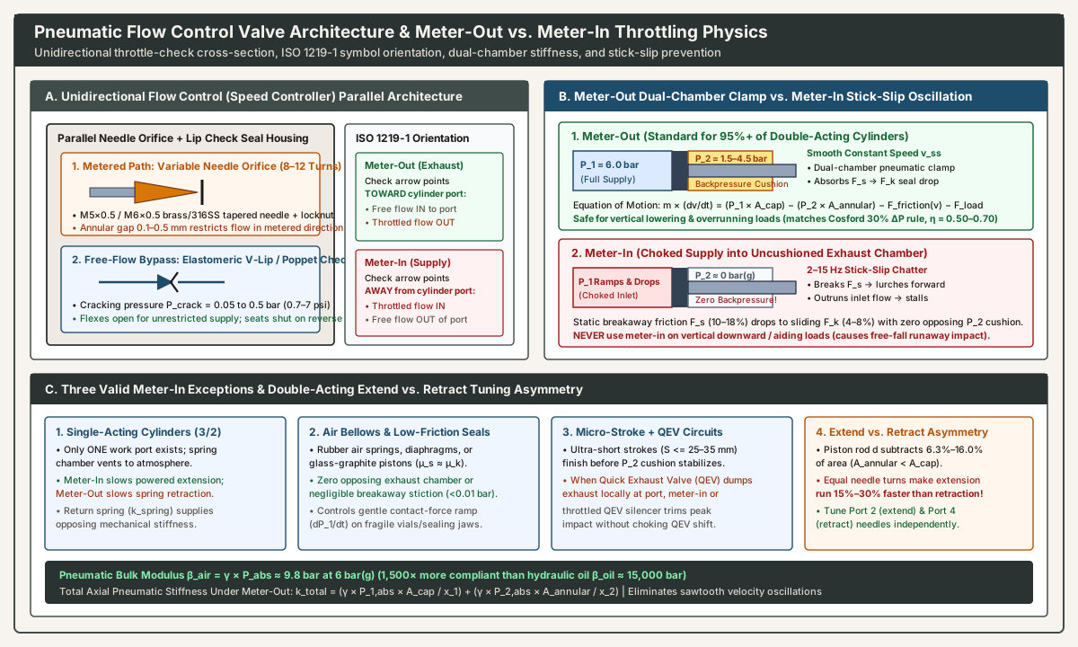
How the Parallel Needle and Lip-Seal Check Operate During a Cycle
- In the Free-Flow Direction (
P_upstream > P_downstream + P_crack): Compressed air pushes the flexible outer lip of the elastomeric V-seal radially inward away from the housing bore (or lifts the check poppet off its seat). Air bypasses the needle throat completely through a wide annular passage with minimal pressure drop (ΔP < 0.2 to 0.5 bar), even if the needle screw is turned100%shut. - In the Metered (Throttled) Direction (
Reverse Flow): Air pressure forces the V-lip seal radially outward against the housing wall (or seats the poppet tightly against its seal ring), blocking the bypass gallery with zero leakage. All escaping or entering air is forced through the narrow annular gap between the tapered needle tip and its orifice seat.
By contrast, a bidirectional throttle valve contains only the variable needle orifice without a parallel check valve (ISO 1219-1 opposing curved restriction lines crossed by a diagonal arrow). Installing a bidirectional needle valve directly on a double-acting cylinder work port is an engineering error: throttling incoming supply air simultaneously with outgoing exhaust air starves the driving chamber during breakaway and delays pressure buildup. Bidirectional needle throttles belong only on single-path blow-off nozzles, pneumatic rotary motors, or Exhaust Ports 3 and 5 of a 5/2 directional valve where supply and exhaust paths are already separated by the valve spool.
Reading ISO 1219-1 Symbols and Body Markings (Meter-Out vs. Meter-In)
Because a meter-out and a meter-in banjo speed controller share the exact same external brass or PBT polymer body casting, installing the wrong variant upside-down is one of the most frequent shop-floor troubleshooting failures (how to read an old pneumatics part number). Under ISO 1219-1 (Fluid power systems and components — Graphic symbols and circuit diagrams):
- Meter-Out Schematic & Body Stamp: The parallel check-valve triangle (or ball-and-seat V-icon) points toward the cylinder work port (
Port 1, the threaded male stud). When supply air travels from the directional valve through the push-to-connect tube collet (Port 2) toward the cylinder (Port 1), the check valve opens for unrestricted entry. When the cylinder exhausts fromPort 1back towardPort 2, the check valve closes and forces exhaust air through the needle restriction. - Meter-In Schematic & Body Stamp: The parallel check-valve triangle points away from the cylinder work port (
from Port 1 toward Port 2). Incoming supply air from the tube collet (Port 2) is blocked by the check seal and must pass through the needle orifice to enter the cylinder, whereas exhausting air leaving the cylinder (Port 1 -> Port 2) pushes the check seal open for unrestricted venting. - Manufacturer Color & Part-Number Coding: Major catalog series distinguish the two configurations via release-button color and suffix codes—for example, SMC
AS-Fseries uses a light-gray release ring and suffix01/02(AS2201F) for meter-out versus a black or orange identification mark and suffix11(AS2211F) for meter-in; Festo designatesGRLAfor exhaust-throttling (meter-out) versusGRLZfor supply-throttling (meter-in); Bosch Rexroth and AVENTICS (CCUand8214series) laser-engrave theISO 1219-1check-and-throttle diagram directly on the swivel body and stamp an arrow pointing along the free-flow direction.
Three Hardware Form Factors and Thread Sealing Standards
- Direct Cylinder-Port Banjo / Swivel Elbow Speed Controller (
Universal / Elbow Type): Threads directly into Cylinder Ports2and4using parallel metric/BSPP threads (M5×0.8,G1/8,G1/4,G3/8,G1/2underISO 228-1with a captive NBR/FKM face seal ring) or tapered threads (R1/8–R1/2underISO 7-1and1/8–1/2 NPTwith factory PTFE sealant). The hollow central banjo stud houses the needle and check seal, while the360°swiveling body aligns the push-to-connect collet (Ø4, Ø6, Ø8, Ø10, Ø12 mmor1/4, 3/8 in.OD tubing) with the machine routing. Engineering Verdict: Gold standard for95%+of double-acting cylinders because it eliminates compliant tubing volume between the piston and the throttling orifice. - Inline Tube-to-Tube / Panel-Mount Speed Controller:
Features push-to-connect tubing collets on both ends (
Port 1andPort 2) plus through-holes or a bulkhead locknut for mounting on an external frame plate when the cylinder sits inside a guarded safety enclosure, high-vibration jaw, or narrow transfer tunnel. Engineering Verdict: Keep the tubing run between the inline flow control and the cylinder port under20 to 30 cm(8 to 12 in.) so trapped tubing volume does not soften the exhaust cushion. - Directional Valve Exhaust-Port Throttle Muffler (
Ports 3 and 5): Combines a porous sintered-bronze (40 µm) or high-density polyethylene (PE) acoustic element with an adjustable throttling screw, threaded directly into Exhaust Port3(rod-end exhaust) and Exhaust Port5(cap-end exhaust) of a5/2solenoid valve. Engineering Verdict: Provides low-cost functional meter-out speed control (supply enters via Port 1 -> 2/4 unthrottled; exhaust exits via Port 2 -> 3 or 4 -> 5 throttled), but places the entire1.0 to 3.0 mconnecting tube upstream of the orifice.
2. Meter-Out vs. Meter-In Pneumatic Physics: Compressibility, Stiction, and Load Control
Why does meter out vs meter in pneumatic circuit design matter so much in compressed air when hydraulic circuits often meter either side interchangeably? The answer lies in the interaction between gas compressibility (β_air) and elastomeric seal stiction (µ_s vs. µ_k).
Governing Equation of Motion and the Stiction Drop (ΔF_friction)
Consider a horizontal or vertical double-acting cylinder of cap area A_cap, annular rod-end area A_annular, moving payload mass m (kg), external resistive load F_load (N), driving chamber gauge pressure P_1, and opposing exhaust chamber gauge pressure P_2. By Newton’s second law:
m × (dv / dt) = (P_1 × A_cap) − (P_2 × A_annular) − F_friction(v) − F_load
As documented in our parent guide (questions to write down before you size a cylinder) and Josh Cosford’s seal velocity analysis (Pneumatic Tips), standard nitrile (NBR), fluoroelastomer (FKM), and polyurethane (TPU) U-cup and O-ring piston seals and rod wipers exhibit two distinct friction regimes:
- Static Breakaway Friction (
F_s = µ_s × N): At rest (v = 0), the elastomer lip squeezes out the microscopic grease film against the aluminum barrel wall, requiring10% to 18%of theoretical cylinder thrust (0.6 to 1.1 barof breakaway differential pressure) to initiate motion. - Kinetic Sliding Friction (
F_k = µ_k × N): Once piston velocity exceeds~15 to 30 mm/sand the hydrodynamic lubricant film shears, sliding friction drops abruptly to4% to 8%of theoretical thrust (0.25 to 0.50 bar).
That sudden force drop at breakaway (ΔF_friction = F_s − F_k, equal to 6% to 10% of cylinder capacity) acts as a step disturbance on the piston. How the pneumatic circuit responds depends entirely on whether the opposing chamber is pressurized (meter-out) or vented to atmosphere (meter-in).
Why Meter-Out Throttling Is Standard on 95%+ of Double-Acting Cylinders
- Dual-Chamber Pneumatic Clamping (
Doubled Axial Stiffness k_total): Under meter-out control, shifting the5/2directional valve floods the driving chamber through the inlet check valve (P_1 ≈ 5.5 to 6.0 bar(g)within10–25 ms). Simultaneously, the opposing chamber’s check seal snaps shut, trapping the exhausting air behind the needle orifice. As the piston begins to move, it compresses that trapped air until opposing backpressureP_2 = 1.5 to 4.5 bar(g)balances the load:P_2,equilibrium = (P_1 × A_cap − F_load − F_k) / A_annularBecause the piston is now sandwiched between two high-pressure gas columns (P_1pushing forward,P_2pushing backward), the total axial pneumatic spring stiffness of the actuator is the sum of both chambers:k_total = (γ × P_1,abs × A_cap / x_1) + (γ × P_2,abs × A_annular / x_2)When breakaway friction drops fromF_stoF_k, the piston cannot lurch forward because any incremental forward displacementΔximmediately compresses the trapped exhaust gas in chamber 2, spikingP_2and braking the piston smoothly at constant terminal velocityv_ss. - Preventing Runaway on Vertical Lowering and Overrunning (
Aiding) Loads: When a vertical hoist cylinder lowers a heavy platen downward, or when an inclined conveyor gate moves with gravity (F_load < 0, an aiding or overrunning load), gravity pulls the piston rod in the direction of travel. Under meter-out control, the lower exhausting chamber trapsP_2 = 3.0 to 6.5+ bar(g)of backpressure, supporting the descending weight on a stiff air cushion so it lowers only as fast as air bleeds through the needle screw. Under meter-in control, the lower chamber vents unrestricted to atmosphere (P_2 = 0 bar(g)), allowing the heavy load to drop in free-fall (pulling a partial vacuum in the upper driving chamber) and slam the bottom end cap at destructive velocity. - Direct Link to Cosford’s
30%Dynamic Pressure Loss and Load Factors (η = 0.70, 0.50): This meter-out backpressure cushionP_2is the exact physical mechanism behind Josh Cosford’s20% to 40%(30%mean:100 psishop air →70 psieffective differential) dynamic bore-sizing rule on cylinder selection questions and theη = 0.70(100–500 mm/s) andη = 0.50(> 500 mm/s) load factors in our double-acting cylinder sizing guide.
Why Meter-In Causes Stick-Slip (Sawtooth Chatter)—and the Three Valid Meter-In Exceptions
Under meter-in control on a standard double-acting cylinder, the opposing exhaust chamber vents directly to atmosphere through its open check valve (P_2 ≈ 0 bar(g)), while incoming supply air is choked through the inlet needle orifice:
- At
t = 0, the piston remains stuck in static friction while inlet pressureP_1ramps up slowly behind the needle restriction until it reaches the breakaway threshold:P_1,breakaway = (F_load + F_s) / A_cap. - The instant the piston breaks free, friction drops from
F_stoF_kwith zero opposing exhaust backpressure (P_2 = 0) to restrain it. The compressed air accumulated in the driving chamber expands like an unbraked spring, launching the piston forward in a rapid jump. - Because the leaping piston sweeps chamber volume
A_cap × Δxmuch faster than the choked inlet needle can replenish air mass, driving pressureP_1plummets below(F_load + F_k) / A_cap, causing the piston to stall mid-stroke. - While stalled, static seal stiction
F_sre-establishes, inlet pressureP_1slowly climbs back toP_1,breakaway, and the violent lurch-and-stall cycle repeats at2 to 15 Hz(stick-slip chatter) all the way down the barrel.
Despite this behavior on standard double-acting cylinders, meter-in speed control is mandatory or preferred in three specific industrial applications:
- Exception 1 — Single-Acting Cylinders (
Spring-Return or Gravity-Return,3/2Valve): A single-acting cylinder (ISO 6432orISO 21287spring-return clamp, gate stop, or label tamper) has only one pneumatic work port connected to the powered chamber; the opposing spring chamber breathes directly to atmosphere through a filter vent. To control the powered extension stroke, you must restrict air entering that single port (meter-in). Meanwhile, the internal mechanical return spring (stiffness k_spring) opposes the piston throughout extension, absorbing theF_s -> F_kfriction drop and preventing stick-slip. To slow the spring-powered retraction stroke, you use a meter-out valve on the same port. When independent extend and retract speed adjustment is required on a single-acting cylinder, plumb two unidirectional flow control valves in series facing opposite directions on the single port. - Exception 2 — Convoluted Air Bellows, Rolling Diaphragms, and Ultra-Low-Friction Glass/Graphite Cylinders (
Force-Ramp Pressing): Rubber air bellows (air springs), rolling-diaphragm actuators, and specialized borosilicate-glass-barrel / graphite-piston cylinders (such as anti-stiction tensioners with< 0.01 barbreakaway friction whereµ_s ≈ µ_k) either have no opposing exhaust chamber or exhibit zero seal stiction jump. In delicate packaging operations—such as pressing hot-melt carton flaps, ultrasonic pouch sealing, or tamping fragile glass vials where the actuator contacts the product within5 to 15 mmand must ramp up clamping force gradually (dP_1 / dtcontrol) rather than hitting with full6 barimpact—meter-in throttling regulates the chamber pressure rise rate cleanly. - Exception 3 — Ultra-Short-Stroke High-Speed Reject Fingers (
S <= 25–35 mm) Paired with Quick Exhaust Valves (QEV): On micro-stroke sorting diverters (10 to 30 mmstroke,< 25 msactuation), a meter-out circuit requires the piston to travel25% to 40%of its stroke just to compress the opposing chamber and establish a stable backpressure cushion—by which time the short stroke is nearly over. When a local Quick Exhaust Valve (QEV) dumps the opposing chamber directly to atmosphere, engineers either install a throttled silencer on the QEV exhaust port or use slight meter-in supply trimming to cap peak impact velocity without delaying exhaust depressurization.
| Comparison Parameter | Meter-Out (Exhaust Throttling) |
Meter-In (Supply Throttling) |
|---|---|---|
| Throttled Airflow Path | Restricts exhaust air leaving the opposing cylinder chamber (check valve opens for free supply in) |
Restricts supply air entering the driving cylinder chamber (check valve opens for free exhaust out) |
ISO 1219-1 Check Arrow Direction |
Check triangle points toward the cylinder port (free flow -> cylinder; metered flow <- cylinder) |
Check triangle points away from the cylinder port (metered flow -> cylinder; free flow <- cylinder) |
Chamber Pressures during Motion (6 bar Shop Air) |
Driving P_1 ≈ 5.5–6.0 bar(g); opposing exhaust cushion P_2 ≈ 1.5–4.5 bar(g) |
Driving P_1 ramps to (F_load + F_s) / A then oscillates; opposing P_2 ≈ 0 bar(g) (atmospheric) |
Axial Pneumatic Stiffness (k_total) |
High (Dual-Chamber Clamp): Pressurized on both piston faces; smooth velocity down to 30–50 mm/s |
Low (Single-Sided Air Spring): Severe 2–15 Hz stick-slip chatter on U-cup/O-ring seals below 250 mm/s |
| Vertical Downward / Overrunning Load Safety | Safe & Controlled: Trapped lower-chamber backpressure P_2 supports gravity loads against free-fall |
UNSAFE (Runaway Hazard): Zero lower-chamber backpressure (P_2 = 0); payload plummets and slams cap |
| Breakaway Response after Solenoid Shift | Immediate breakaway once exhaust chamber begins bleeding (size bore with η = 0.50–0.70 to overcome P_2) |
Delayed breakaway lag while inlet line and dead volume slowly fill to P_1,breakaway, followed by lurch |
| Primary Packaging Line Applications | 95%+ of Double-Acting Cylinders: ISO 15552, ISO 6432, ISO 21287, and rodless transfers, lifts, pushers |
Single-Acting (3/2) Cylinders, air bellows/diaphragms, low-friction glass/graphite cylinders, force ramping |
Extend vs. Retract Speed Asymmetry on Standard Rodded Cylinders (A_cap vs. A_annular)
As quantified in our double-acting pneumatic cylinder sizing guide, the piston rod (diameter d) subtracts 6.3% to 16.0% of the piston face area on the rod end (A_annular = π × (D² − d²) / 4 < A_cap = π × D² / 4). This geometric asymmetry directly affects meter-out tuning:
- During Extension (
Outstroke): Full supply pressure acts on the larger cap-end face (A_cap), while the piston pushes a smaller rod-end air volume (V_rod = A_annular × S) out through the rod-end (Port 2) meter-out speed controller. - During Retraction (
Instroke): Supply pressure acts on the16%smaller annular face (A_annular), while the piston must expel a16%larger cap-end air volume (V_cap = A_cap × S) out through the cap-end (Port 4) meter-out speed controller.
Consequently, if a technician sets both meter-out needle screws to the exact same number of turns (for instance, 5.0 turns open), the cylinder will extend 15% to 30% faster than it retracts. Always tune Port 2 (rod-end banjo, which governs extension speed) and Port 4 (cap-end banjo, which governs retraction speed) independently with the payload attached.
3. ISO 6358 Sonic Conductance (C) and Critical Pressure Ratio (b) Velocity Sizing
Sizing a pneumatic flow control valve by matching thread size alone (putting a G1/4 speed controller on every G1/4 cylinder port) works for moderate speeds (100 to 400 mm/s), but fails on high-speed packaging actuators (> 500 mm/s) or compact valves where internal banjo passages choke airflow. Modern pneumatic component sizing uses ISO 6358 (Pneumatic fluid power — Determination of flow-rate characteristics of components using compressible fluids, harmonized with JIS B 8390).
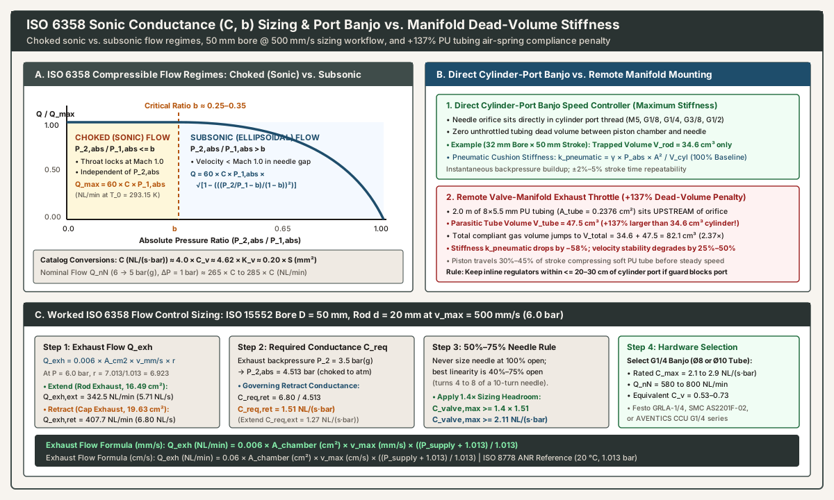
Why ISO 6358 Uses Two Parameters (C and b) Instead of a Single Hydraulic K_v or C_v
As explained in Machine Design: Sorting Out the Truth About Pneumatic Standards and the MathWorks Simscape ISO 6358 Orifice Documentation, liquids are incompressible, so water flow through an orifice scales continuously with √ΔP. In a compressible gas (air, γ = 1.4), increasing the pressure drop across a needle valve accelerates air in the narrowest vena contracta throat only until the gas reaches the local speed of sound (Mach 1.0 ≈ 343 m/s at 20 °C). Once the throat hits Mach 1.0, downstream pressure waves cannot propagate upstream through the sonic throat—the orifice is choked (sonic), and lowering downstream pressure P_2 further produces zero additional volumetric flow.
ISO 6358 characterizes every pneumatic flow path using two experimentally measured parameters referenced to ISO 8778 Standard Reference Atmosphere (ANR: T_0 = 293.15 K / 20 °C, P_0 = 1.01325 bar(a), 65% RH):
- Sonic Conductance
C(NL/(s·bar)ordm³/(s·bar)ANR): The maximum choked free-air volume flow rate passing through the component per bar of absolute upstream stagnation pressureP_1,abs(= P_1,gauge + 1.013 bar) atT_0 = 20 °C. MultiplyingCby60givesNL/(min·bar). - Critical Pressure Ratio
b(dimensionless, 0 < b < 1): The threshold absolute pressure ratioP_2,abs / P_1,absat which airflow transitions between choked sonic flow and subsonic ellipsoidal flow. While an ideal frictionless nozzle in air hasb_ideal = 0.528, turbulent vena contracta losses and right-angle banjo drillings in real pneumatic flow control valves yieldb = 0.15 to 0.35in the metered needle direction andb = 0.25 to 0.45in the free-flow check direction (SMC Corporation: Valve Flow Rate Characteristics and ISO 6358 Calculation Guide).
Exact ISO 6358 Choked (Sonic) and Subsonic Flow Equations
Let P_1,abs = P_1,gauge + 1.013 (bar(a)) be absolute pressure upstream of the speed controller (inside the exhausting cylinder chamber during meter-out control) and P_2,abs = P_2,gauge + 1.013 (bar(a)) be absolute downstream pressure (near 1.013 bar(a) when venting through a short tube and 5/2 valve to atmosphere):
- Regime 1 — Choked (Sonic) Flow (
P_2,abs / P_1,abs <= b): When a cylinder exhaust chamber atP_1,gauge = 3.5 bar(P_1,abs = 4.513 bar) vents to atmospheric exhaust (P_2,abs ≈ 1.013 bar), the pressure ratio is1.013 / 4.513 = 0.224 <= b. The needle throat is choked at Mach1.0, and free-air flow depends only onCandP_1,abs:Q_max (NL/s) = C × P_1,abs × √(293.15 / T_1)Q_max (NL/min) = 60 × C × (P_1,gauge + 1.013)(atT_1 = 20 °C = 293.15 K) - Regime 2 — Subsonic Flow (
P_2,abs / P_1,abs > b): When the pressure ratio across the orifice exceedsb, flow follows theISO 6358ellipsoidal curve:Q (NL/s) = C × P_1,abs × √[ 1 − (( (P_2,abs / P_1,abs) − b ) / (1 − b))² ]Q (NL/min) = 60 × Q (NL/s)
Cross-Standard Conversion Formulas (C, C_v, K_v, Effective Area S, and Q_nN)
When comparing datasheets across European (Bosch Rexroth, AVENTICS, Festo), Japanese (SMC), and North American (Parker, Humphrey, Ross) catalogs (SMC ISO 6358 Guide and Machine Design), use these exact engineering conversions:
- Sonic Conductance
C(NL/(s·bar)) and Effective Orifice AreaS(mm²,JIS B 8390):C (NL/(s·bar)) = 0.20 × S (mm²)andS (mm²) = 5.0 × C - Sonic Conductance
C(NL/(s·bar)) and North American Flow CoefficientC_v(ANSI/NFPA T3.21.3):C (NL/(s·bar)) ≈ 4.00 × C_v(orC = 3.69 × C_vvia SMC’sS = 18.45 × C_vconvention) andC_v ≈ 0.25 × C - Sonic Conductance
Cand Metric Water Flow FactorK_v(m³/hof water atΔP = 1 bar):C_v = 1.156 × K_vandC (NL/(s·bar)) ≈ 4.62 × K_v - Standard Nominal Flow
Q_nN(NL/minmeasured atP_1 = 6 bar(g) -> P_2 = 5 bar(g),ΔP = 1 bar): AtP_1,abs = 7.013 bar,P_2,abs = 6.013 bar(P_2,abs / P_1,abs = 0.857 > b), pluggingb = 0.25 to 0.35into the subsonic equation yields:Q_nN (NL/min) ≈ 265 × Cto285 × C(rule of thumb:C ≈ Q_nN / 275)
Step-by-Step Cylinder Velocity (v_max) to Flow Control Conductance (C_req) Sizing
To drive a double-acting cylinder of exhausting chamber area A_chamber (A_annular on extension, A_cap on retraction) at a target peak steady-state mid-stroke velocity v_max (typically 1.3× to 1.4× average velocity S / t_stroke, matching Cosford’s 0.70 acceleration factor in Pneumatic Tips), the meter-out speed controller on the exhausting port must pass the displaced cylinder volume compressed at supply pressure ratio r = (P_supply + 1.013) / 1.013:
- With
A_chamberincm²andv_maxinmm/s:Q_exh (NL/min) = 0.006 × A_chamber (cm²) × v_max (mm/s) × ((P_supply + 1.013) / 1.013) - With
A_chamberincm²andv_maxincm/s(1 cm/s = 10 mm/s):Q_exh (NL/min) = 0.06 × A_chamber (cm²) × v_max (cm/s) × ((P_supply + 1.013) / 1.013) - Required Sonic Conductance (
C_req) and the50%–75%Needle-Open Rule (1.4×Multiplier): A fine-pitch needle valve delivers linear flow sensitivity between40% and 75%open (turns 4 to 8 of a 10-turn screw). Over the final20%of travel (turns 8 to 10), the needle cone clears the orifice throat and loses throttling resolution. Therefore, divideQ_exh / 60(NL/s) by absolute exhaust chamber pressureP_exh,abs = P_exh,gauge + 1.013(typically3.5 + 1.013 = 4.513 bar(a)under meter-out cushion equilibrium) and apply a1.4×sizing headroom factor:C_req (NL/(s·bar)) = Q_exh (NL/min) / [ 60 × (P_exh,gauge + 1.013) ]C_valve,max >= 1.4 × C_req
Worked Sizing Example: ISO 15552 50 mm Bore Cylinder at v_max = 500 mm/s (6.0 bar)
Size the direct-port meter-out banjo speed controllers for an ISO 15552 D = 50 mm bore, d = 20 mm rod double-acting cylinder (A_cap = 19.63 cm², A_annular = 16.49 cm² from our double-acting cylinder sizing table) operating at P_supply = 6.0 bar(g) (r = 6.923) that must achieve a peak mid-stroke velocity of v_max = 500 mm/s (50 cm/s) in both directions:
- Extension Exhaust Flow (
Rod Chamber Exhausting through Port 2,A_annular = 16.49 cm²):Q_exh,ext = 0.006 × 16.49 cm² × 500 mm/s × 6.923 = 342.5 NL/min(5.71 NL/s). - Retraction Exhaust Flow (
Cap Chamber Exhausting through Port 4,A_cap = 19.63 cm²):Q_exh,ret = 0.006 × 19.63 cm² × 500 mm/s × 6.923 = 407.7 NL/min(6.80 NL/s). - Required Valve Sonic Conductance (
at P_exh,gauge = 3.5 bar -> P_exh,abs = 4.513 bar(a)):- Extend (
Port 2):C_req,ext = 5.71 NL/s / 4.513 bar = 1.27 NL/(s·bar). - Retract (
Port 4, governing):C_req,ret = 6.80 NL/s / 4.513 bar = 1.51 NL/(s·bar). - Applying the
1.4×mid-scale adjustment multiplier (so the needle runs at ~70% open):C_valve,max >= 1.4 × 1.51 = 2.11 NL/(s·bar)(Q_nN >= 580 NL/min,C_v >= 0.53,S >= 10.6 mm²).
- Extend (
- Catalog Hardware Selection:
A standard
G1/4cylinder-port banjo speed controller with anØ8 mmorØ10 mmpush-in collet—such as FestoGRLA-1/4-QS-8-D(C = 2.2 NL/(s·bar)), SMCAS2201F-02-08S/10S(C = 2.1–2.6 NL/(s·bar)), or AVENTICSCCU G1/4(Q_nN = 600–710 NL/min)—satisfiesC_valve,max >= 2.11 NL/(s·bar)with smooth adjustment authority on turns5 to 7.
Master Lookup Table: ISO 6358 Flow Control Conductance (M5 to G1/2) and Cylinder Speed Limits
| Port Thread & Recommended Tube OD | Matching ISO 6432 / ISO 15552 Cylinder Bores |
Fully Open Metered Sonic Conductance C (NL/(s·bar)) |
Critical Pressure Ratio b (Metered) |
Standard Nominal Flow Q_nN (6 -> 5 bar, NL/min) |
Equivalent C_v and Effective Area S (mm²) |
Max Recommended Exhaust Flow at 70% Open (NL/min) |
Representative Industrial Catalog Series (Meter-Out) |
|---|---|---|---|---|---|---|---|
M5 × 0.8 (Ø4 mm or Ø6 mm PU Tube) |
ISO 6432 8, 10, 12, 16 mm |
0.35 to 0.50 |
0.20 to 0.28 |
95 to 135 NL/min |
C_v = 0.09–0.13 (S = 1.8–2.5 mm²) |
110 to 160 NL/min (16 mm bore up to 800 mm/s) |
Festo GRLA-M5-QS-4/6, SMC AS1201F-M5-04/06, AVENTICS 8214 M5 |
G1/8 (Ø6 mm or Ø8 mm PU Tube) |
ISO 6432 20, 25 mm & ISO 15552 32 mm |
1.10 to 1.60 |
0.22 to 0.30 |
300 to 440 NL/min |
C_v = 0.28–0.40 (S = 5.5–8.0 mm²) |
350 to 500 NL/min (32 mm bore up to 750 mm/s) |
Festo GRLA-1/8-QS-6/8, SMC AS2201F-01-06/08, AVENTICS CCU G1/8 |
G1/4 (Ø8 mm or Ø10 mm PU Tube) |
ISO 15552 40 mm & 50 mm |
2.10 to 2.90 |
0.25 to 0.32 |
580 to 800 NL/min |
C_v = 0.53–0.73 (S = 10.5–14.5 mm²) |
650 to 900 NL/min (50 mm bore up to 700 mm/s) |
Festo GRLA-1/4-QS-8/10, SMC AS2201F-02-08/10, AVENTICS CCU G1/4 |
G3/8 (Ø10 mm or Ø12 mm PU Tube) |
ISO 15552 63 mm & 80 mm |
4.20 to 5.40 |
0.25 to 0.35 |
1,150 to 1,480 NL/min |
C_v = 1.05–1.35 (S = 21.0–27.0 mm²) |
1,300 to 1,700 NL/min (63 mm bore up to 650 mm/s) |
Festo GRLA-3/8-QS-10/12, SMC AS3201F-03-10/12, AVENTICS CCU G3/8 |
G1/2 (Ø12 mm or Ø16 mm PU Tube) |
ISO 15552 100 mm & 125 mm |
7.50 to 9.80 |
0.28 to 0.38 |
2,050 to 2,700 NL/min |
C_v = 1.88–2.45 (S = 37.5–49.0 mm²) |
2,300 to 3,100 NL/min (100 mm bore up to 550 mm/s) |
Festo GRLA-1/2-QS-12, SMC AS4201F-04-12, AVENTICS CCU G1/2 |
4. Mounting Location Physics: Port Banjo vs. Manifold Tubing Dead-Volume Penalty (+137%)
In our double-acting cylinder air-consumption analysis, we showed that long polyurethane (PU) tubing runs between the 5/2 directional valve and the cylinder waste 16% to 38% of compressed air per cycle. When it comes to speed controller cylinder mounting, placing the flow restriction at the remote valve manifold instead of directly in the cylinder port causes an even more severe dynamic control penalty.
How Upstream Tubing Volume Softens the Pneumatic Cushion (k_pneumatic)
The axial pneumatic stiffness k_pneumatic (N/m) of the exhausting chamber under meter-out control is inversely proportional to the total trapped gas volume (V_trapped) upstream of the needle orifice:
k_pneumatic = (γ × P_2,abs × A_chamber²) / (V_chamber + V_tube,upstream)
- Case 1 — Direct Cylinder-Port Banjo Mounting (
V_tube,upstream = 0): When the banjo speed controller screws directly into the cylinder head port (Port 2), the needle orifice sits immediately at the boundary of the cylinder chamber. On anISO 15552D = 32 mmbore,d = 12 mmrod,S = 50 mm(5.0 cm) stroke indexing or reject cylinder (A_annular = 6.91 cm²), the maximum trapped gas volume upstream of the needle is strictly the rod chamber volume:V_trapped,banjo = A_annular × S = 6.91 cm² × 5.0 cm = 34.6 cm³ - Case 2 — Remote Manifold Exhaust Throttle or Manifold-Mounted Flow Control (
L_tube = 2.0 m): If the engineer removes the port banjos and throttles the cylinder using exhaust-port needle mufflers on Ports3and5of a5/2valve island located2.0 m(200 cm) away connected via standard8 × 5.5 mmPU tubing (ID = 5.5 mm,A_tube = 0.2376 cm²), that entire2.0 mtube now sits upstream of the needle orifice:V_tube,upstream = 0.2376 cm² × 200 cm = 47.5 cm³V_trapped,manifold = 34.6 cm³ + 47.5 cm³ = 82.1 cm³(+137%more compliant gas volume!)
Because 82.1 cm³ is 2.37× larger than 34.6 cm³, remote manifold throttling cuts exhaust cushion stiffness k_pneumatic by 57.8% (further worsened by radial hoop expansion of flexible Shore 98A polyurethane tubing under pressure). During each stroke, the piston must travel 30% to 45% of its 50 mm stroke merely compressing the 47.5 cm³ tube volume before exhaust pressure P_2 rises high enough to choke the manifold muffler—degrading stroke-time repeatability by 25% to 50% whenever conveyor friction or shop air pressure fluctuates.
Engineering Placement Rule: Always thread meter-out banjo speed controllers directly into the cylinder ports (Port 2 and Port 4). Use inline tube-to-tube flow controls only when safety guarding or > 80 °C heat-sealing tooling prevents port access, and mount those inline regulators within <= 20 to 30 cm of the cylinder body.
5. Quick Exhaust Valves (QEV) for High-Speed Packaging Reject Actuators (< 30–50 ms)
On a high-speed bottling or canning line running 200 containers/min (3.33 containers/s, or a 300 ms container-to-container center pitch, as detailed on our checklist from a bad container to the reject ram citing Accutek Packaging’s Inspection-Rejection Station), a downstream pneumatic reject cylinder (32 mm or 40 mm bore, 50 to 100 mm stroke) must extend to push the defective container off the belt and retract completely clear of the conveyor before the next good bottle arrives. That requires single-stroke transit times of 25 to 50 ms (peak piston speeds of 1,000 to 2,000 mm/s).
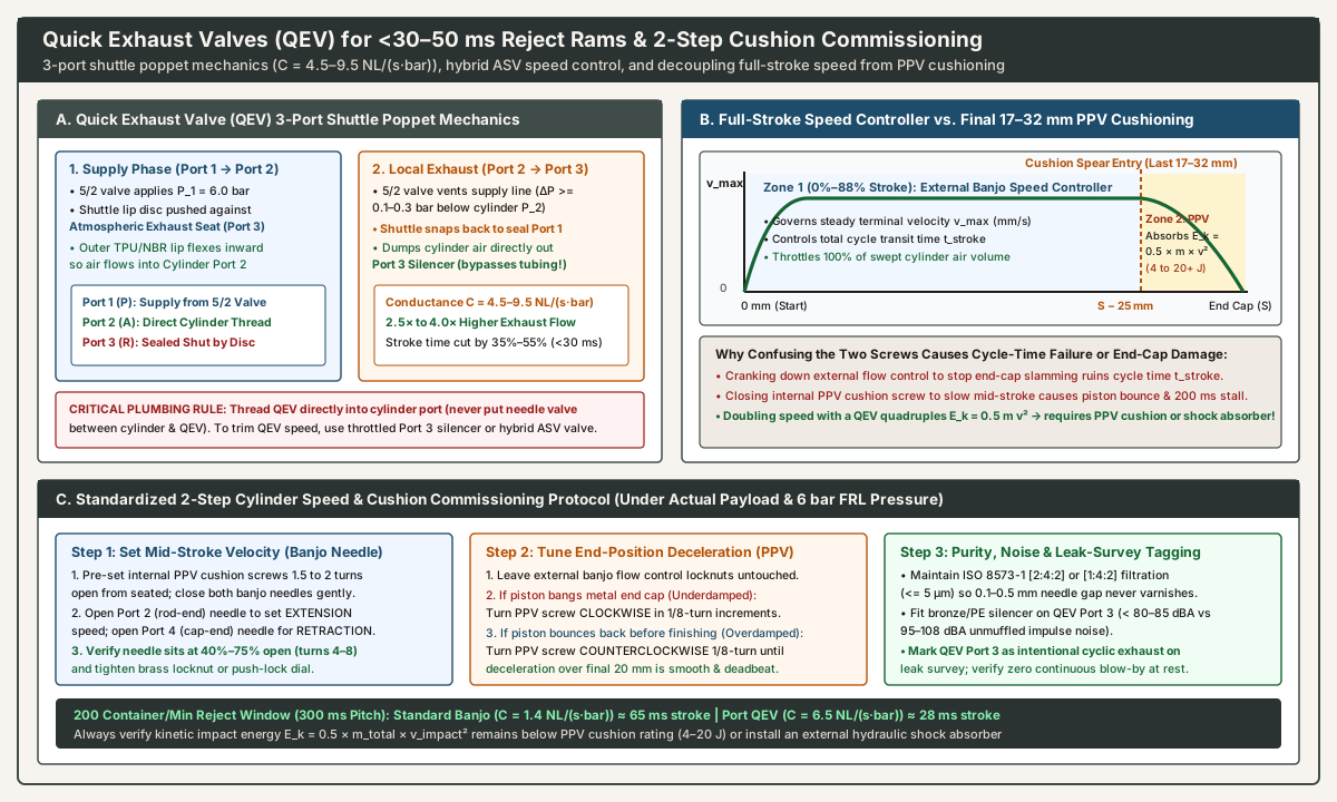
Why Standard Banjo Speed Controllers Choke Above 800–1,000 mm/s
Even if you unscrew a standard G1/8 or G1/4 banjo speed controller 100% open (C = 1.3 to 2.2 NL/(s·bar)), the exhausting air from the cylinder must still flow backward through:
- The banjo body orifice (
C ≈ 1.5 NL/(s·bar)), 1.5 to 2.5 mof8 × 5.5 mmpolyurethane tubing (frictional pressure drop ΔP ≈ 0.8–1.5 bar),- The internal spool passages of the
5/2directional solenoid valve (C ≈ 2.0–3.5 NL/(s·bar)), and - The manifold exhaust silencer (
Port 3orPort 5).
Combined series conductance (1 / C_total² ≈ 1 / C_banjo² + 1 / C_tube² + 1 / C_valve²) drops effective exhaust conductance below 0.8 to 1.1 NL/(s·bar), trapping 2.5 to 4.0 bar of residual backpressure inside the cylinder and capping terminal piston speed so a 32 × 80 mm stroke takes 60 to 85 ms—clipping the neighboring good container on a 200 container/min line.
Quick Exhaust Valve (QEV) 3-Port Shuttle Poppet Mechanics
A Quick Exhaust Valve (QEV) (such as Festo SEU/SE, SMC AQ series, or Bosch Rexroth / AVENTICS 5735 / QR1 quick-exhaust valves, described in Pneumatic Tips: What are Pneumatic Valves?) is a 3-port pressure-differential shuttle valve threaded directly into the cylinder work port (Port 2 / A = cylinder port; Port 1 / P = supply line from 5/2 directional valve; Port 3 / R = oversized local atmospheric exhaust port fitted with a high-flow silencer):
- Supply Phase (
Port 1 -> Port 2, Cylinder Extending or Pressurizing): When the5/2solenoid valve energizes (P_1 = 6.0 bar), incoming air pressure pushes the internal flexible polyurethane (TPU) or nitrile (NBR) lip-poppet disc tightly against the large atmospheric exhaust seat (Port 3), sealingPort 3shut. Simultaneously, the outer elastomeric periphery of the shuttle disc deflects inward, allowing supply air to flow fromPort 1into Cylinder Port2. - Local Dump Phase (
Port 2 -> Port 3, Cylinder Exhausting): The instant the5/2valve shifts to vent the supply tube (dropping Port 1 pressure by >= 0.10 to 0.30 bar below Cylinder Port 2 pressure), the higher pressure inside the cylinder chamber snaps the shuttle disc backward against the inlet seat (Port 1). This seals off the long return tube and opens a wide, direct exhaust passage from Cylinder Port2straight out Atmospheric Port3.
In the local exhaust direction (Port 2 -> Port 3), a G1/8 or G1/4 Quick Exhaust Valve delivers a sonic conductance of C = 4.5 to 9.5 NL/(s·bar) (Q_nN = 1,200 to 2,600 NL/min)—2.5× to 4.0× higher than a standard speed controller while completely bypassing the 1.5 m tubing and 5/2 directional valve restrictions. Installing a QEV on the rod-end port (Port 2) of a 32 × 80 mm reject cylinder cuts extension transit time by 35% to 55% (reducing a 65 ms stroke down to 28 ms).
Four Mandatory Engineering Rules When Applying Quick Exhaust Valves
- Never Plumb a Standard Flow Control Valve Between the Cylinder Port and the QEV (
Port 2): A QEV relies on a rapid pressure differential (P_2 > P_1 + 0.2 bar) between the cylinder chamber and the supply tube to snap its internal shuttle disc onto thePort 1seat. Placing a needle restriction between the cylinder port andPort 2of the QEV chokes exhaust flow before it reaches the QEV and prevents the shuttle poppet from shifting cleanly. Thread the QEV male stud (Port 2) directly into the cylinder port bushing. - How to Regulate Speed on a QEV Circuit (
Throttled Port 3 Silenceror HybridASVValve): If an unthrottled QEV accelerates the reject ram faster than required, regulate its exhaust rate by screwing an adjustable throttle muffler into the QEV’s atmospheric exhaust port (Port 3), or specify a Quick-Exhaust Speed Controller (such as the SMCASV310F / ASV410F / ASV510Fseries), which integrates a high-conductance local QEV shuttle (C = 2.5 to 6.2 NL/(s·bar)) with a calibrated rotary meter-out needle and built-in acoustic silencer in one banjo housing. - End-of-Stroke Kinetic Energy (
E_k = 0.5 × m × v²) Quadruples When Velocity Doubles: As proven in our double-acting cylinder cushioning guide, kinetic impact energy scales with the square of terminal velocity (v_impact²). Cutting stroke time in half with a QEV doublesv_impactand quadruplesE_k. Never fit a QEV to a cylinder equipped only with fixed elastomer (P) bumper pads (0.4 to 1.2 Jcapacity) unless the cylinder stops against an external hydraulic shock absorber or uses properly tunedPPVadjustable pneumatic cushions (4 to 20+ J). - Impulse Noise Attenuation (
OSHA 90 dBA) and Ultrasonic Leak-Survey Tagging: Dumping6 barcylinder air directly to atmosphere through an open QEV port generates95 to 108 dBAimpulse noise spikes and ejects pipe scale at high velocity. Always thread a high-flow sintered bronze or polyethylene safety silencer into QEVPort 3(reducing noise to 78–84 dBA). On the plant compressed-air leak survey, mark every QEV as an intentional cyclic exhaust, then listen with an ultrasonic camera while the cylinder sits stationary at home (pressurized) to verify that a nicked QEV shuttle disc is not leaking air continuously outPort 3.
6. Commissioning & Troubleshooting: Decoupling Speed Controllers from PPV Cushions
During packaging line startups, maintenance technicians frequently confuse the external port flow control valve (speed controller cylinder) with the internal end-of-stroke pneumatic cushion screw (PPV) built into the cylinder head and cap castings (Power & Motion: All About Cylinder Cushioning). Cranking down the external banjo needle to stop end-cap slamming ruins the machine’s cycle time, whereas closing the internal PPV cushion screw to slow mid-stroke speed causes the piston to bounce backward off a trapped air pocket 25 mm before the end of travel.
Functional Separation Along the Stroke (0%–88% vs. Final 17–32 mm)
- External Meter-Out Speed Controller (
0% to 100%of Stroke): Screwed into Cylinder Ports2and4. Controls the mass flow rate of100%of the swept cylinder volume across the entire stroke length, setting the steady-state terminal velocityv_max(mm/s) and total transit timet_stroke(ms). - Internal Pneumatic Cushion
PPV(Final 17 to 32 mm/Last 5%–15%of Stroke): Recessed brass or stainless needle screw flush-mounted in the cylinder head and cap next to the port. Does nothing during the first85% to 90%of travel while exhaust air exits freely through the main port. Only when the piston’s tapered cushion spear (boss) enters the head cushion seal over the final17 to 32 mmof stroke does the main exhaust path close—forcing the last trapped pocket of air (5 to 25 cm³) to bleed through thePPVneedle screw to decelerate payload kinetic energy (E_k = 0.5 × m × v_impact²) smoothly to zero right before metal-to-metal contact.
Standardized Two-Step Field Commissioning Sequence
Always tune cylinder speed and cushioning under actual operating FRL pressure (e.g., 6.0 bar) and full payload mass—never on an unloaded rod or reduced test air:
- Step 1 — Establish Safe Baseline and Tune Mid-Stroke Velocity (
External Banjo Needles):- Before cycling power, set both internal
PPVcushion screws on the cylinder heads to1.5 to 2.0 turns openfrom fully seated (providing moderate baseline deceleration). - Turn both external meter-out banjo speed controller needles clockwise until gently seated (
do not over-torque brass needle tips against the seat), then open each needle1.5 turns. - Cycle the
5/2directional valve and progressively open Port 2 (rod-end banjo) to dial in the extension speed, and Port 4 (cap-end banjo) to dial in the retraction speed, until the actuator meets its required stroke timet_strokesmoothly without stick-slip. Lock both knurled brass locknuts (or push-lock caps).
- Before cycling power, set both internal
- Step 2 — Tune End-of-Stroke Deceleration (
Internal PPV Cushion Screws):- Leave the locked external banjo speed controllers untouched. Observe the final
25 mmof piston travel at both ends of the stroke: - If the piston hits the end cap with an audible metallic clack (
Underdamped): Turn the corresponding head/capPPVcushion screw clockwise (closing) in1/8-turnincrements until impact noise disappears. - If the piston decelerates abruptly, reverses/bounces backward
3–8 mm, and hesitates for100–300 msbefore creeping into the end cap (Overdamped Cushion Bounce): Trapped cushion pressure is spiking above driving forceP_1 × A. Turn thePPVcushion screw counterclockwise (opening) in1/8-turnincrements until the piston settles deadbeat into the end position without rebound.
- Leave the locked external banjo speed controllers untouched. Observe the final
Industrial Diagnostic Matrix: Flow Control & Speed Controller Failure Modes
| Observed Field Symptom | Root Physical Cause | Diagnostic Verification Check | Corrective Engineering Action |
|---|---|---|---|
Sawtooth Stick-Slip Chatter (2–15 Hz Lurching & Stalling) |
1. Meter-in valve installed by mistake on double-acting cylinder (P_2 ≈ 0 bar).2. Excessively long PU tubing (> 2 m) between cylinder and remote manifold throttle.3. Undersized cylinder bore ( load > 75% of F_th, high F_s -> F_k stiction ratio). |
1. Check ISO 1219-1 arrow on banjo body (must point toward port for meter-out).2. Measure tubing length upstream of throttle. 3. Check dynamic load factor η (cylinder force guide). |
1. Replace with meter-out banjo (GRLA, AS-F meter-out).2. Move banjo directly into cylinder work port. 3. Upsize cylinder bore to meet η = 0.50–0.70 or switch to U-cup low-friction seals. |
Turning Needle Screw Has Zero Effect on Cylinder Speed (Runs at Full Speed) |
1. Meter-in valve installed where meter-out was intended (or vice versa on single-acting 3/2).2. Internal elastomeric V-lip check seal is torn, dislodged, or swollen by synthetic compressor oil, allowing exhaust air to bypass the needle. 3. Needle tip adjusted past 80% open (out of orifice throat). |
1. Turn needle 100% clockwise (closed): a healthy meter-out valve will stall/lock the cylinder completely.2. If cylinder still moves with needle seated shut, the internal check lip is bypassing. |
1. Verify check arrow direction. 2. Replace damaged speed controller and audit upstream coalescing filters ( ISO 8573-1 [2:4:2] on air preparation). |
Extension Runs 20%–30% Faster Than Retraction at Equal Needle Turns |
Geometric piston-rod area asymmetry (A_annular is 6.3%–16.0% smaller than A_cap), so extension sweeps less rod-end exhaust air with higher cap-end driving thrust. |
Compare Port 2 (rod) and Port 4 (cap) needle turns; check bore/rod ratio in ISO 15552 table. |
Normal double-acting physics: close Port 2 (rod-end) needle slightly or open Port 4 (cap-end) needle to balance extend and retract velocities. |
Cylinder Starts Moving 150–400 ms Late After Solenoid Fires (Breakaway Lag) |
1. Opposite-end PPV cushion check seal or banjo check lip is sticking (high cracking pressure), forcing incoming supply air through the needle.2. Oversized 2–3 m tubing dead volume must fill from 0 to 6 bar before reaching P_breakaway. |
Tee a pressure gauge at the driving cylinder port and observe pressure rise rate dP_1 / dt when 5/2 valve shifts. |
1. Clean or replace banjo fitting with low-cracking-pressure (0.05–0.15 bar) lip check.2. Shorten PU tubing (<= 0.5 m) and verify 5/2 valve C rating matches Q_peak. |
Speed Drifts Slower Over Shifts (Requires Constant Needle Re-Adjustment) |
1. Knurled locknut vibrated loose. 2. Wet air or degraded compressor lubricant ( varnish) + > 5 µm pipe rust clogging the 0.1–0.3 mm annular needle gap.3. Adiabatic expansion icing across choked orifice when dew point is high. |
1. Check locknut torque. 2. Unscrew needle and inspect tip for brown oil varnish, PTFE tape shreds, or water droplets. |
1. Use push-lock rotary dial controllers. 2. Maintain +3 °C refrigerated or -40 °C desiccant pressure dew point (compressed air dryer selection) + 5 µm / 0.01 mg/m³ filtration. |
Piston Bounces Backward 5 mm Before Finishing Stroke (Cushion Rebound) |
Internal PPV cushion needle screw is closed too tight (overdamped), trapping a high-pressure spike in the last 20 mm that exceeds driving force. |
Observe whether hesitation occurs 20–30 mm before the end cap (cushion spear entry point). |
Back out the internal PPV cushion screw counterclockwise 1/8 to 1/4 turn (do not open the external port flow control). |
Continuous Hiss From QEV Exhaust (Port 3) or Banjo Swivel at Rest |
1. Worn QEV polyurethane shuttle disc failing to seal Port 3 while pressurized, or insufficient ΔP from undersized supply line.2. Extruded NBR face seal on G-thread banjo or scratched push-in tube OD. |
Scan stationary pressurized actuator with ultrasonic detector during leak survey walk. | 1. Replace QEV shuttle cartridge and ensure supply valve C >= QEV inlet demand.2. Cut tube square with guillotine cutter and replace G-thread captive sealing ring. |
Air Preparation Requirements for Needle Orifice and Check-Seal Longevity (ISO 8573-1)
Because a throttled pneumatic flow control valve operates with an annular needle clearance of only 0.10 to 0.40 mm (100 to 400 µm) and relies on a thin elastomeric check lip flexing every cycle while air expands adiabatically through Mach 1.0 (dropping local gas temperature by 15 to 35 °C across the vena contracta), upstream air quality directly governs velocity stability:
- Particulate Filtration (
ISO 8573-1Class1or2,<= 5 µm): Rust scale, desiccant dust, or shredded PTFE thread tape larger than5 to 40 µmwedges in the needle throat or lodges under the check lip—either shifting the calibrated speed setting or holding the check valve open. Always use captive elastomeric face seals on parallelG(BSPP) andM5threads rather than wrapping PTFE tape over the first two threads (air preparation questions for a packaging line). - Moisture & Dew Point Control (
ISO 8573-1Class4+3 °Cor Class2-40 °C): If saturated compressed air enters a choked meter-out needle or Quick Exhaust Valve, adiabatic cooling condenses liquid water droplets that wash out factory barium/lithium cylinder grease (raising static breakaway friction F_s by 2× to 3×and inducing stick-slip even on meter-out circuits). Select and size upstream drying per our compressed air dryer selection guide.