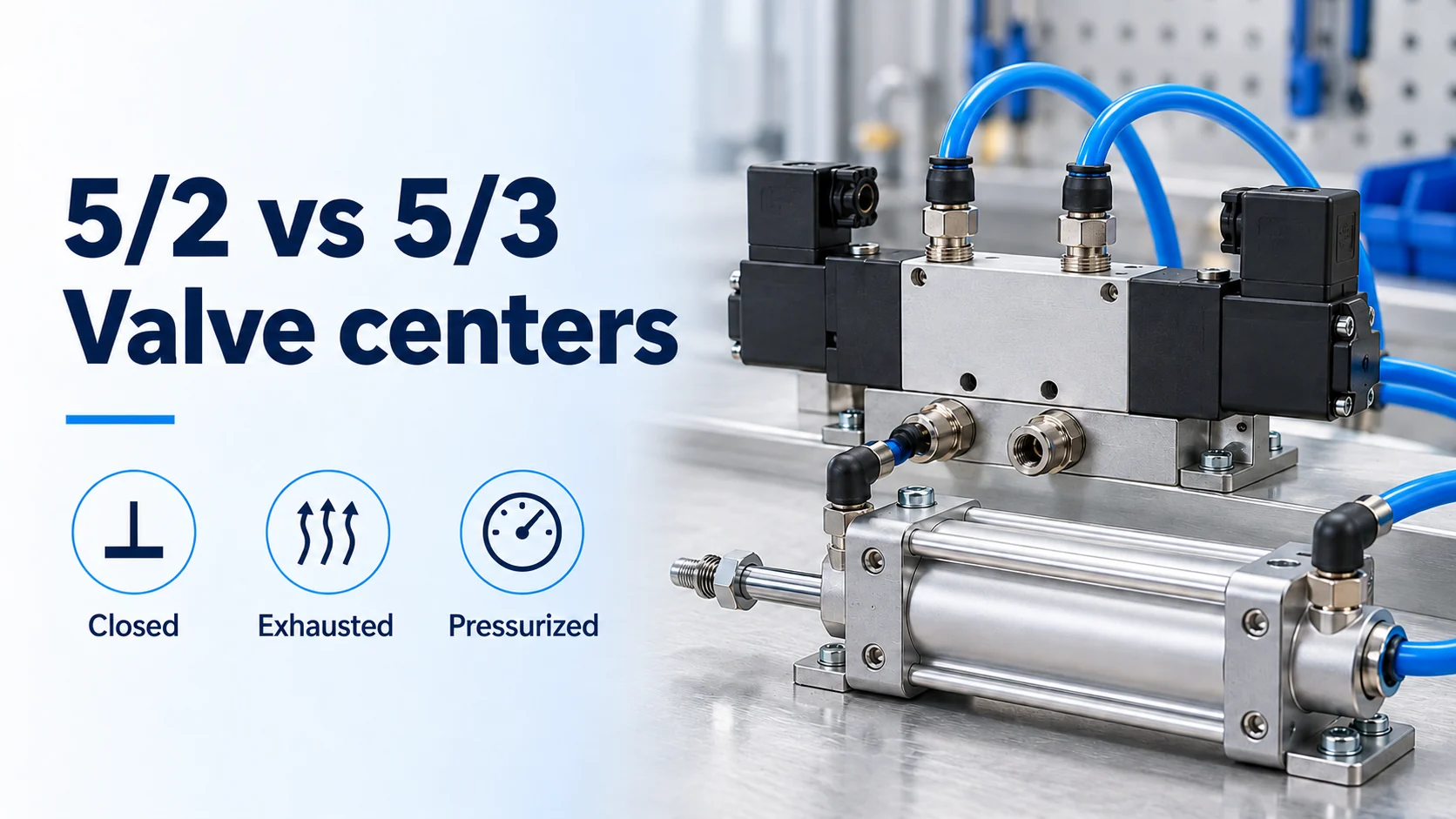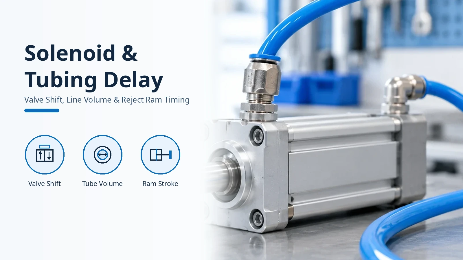
Accounting for solenoid valve tubing delay is essential when commissioning a high-speed packaging reject ram or sorting diverter where milliseconds separate a clean reject from a mis-hit container. When an inspection sensor triggers a downstream reject pusher, the total pneumatic reject cylinder response time combines the electrical coil delay, directional valve spool or poppet shifting time, viscous pressure-filling lag across the valve to cylinder tubing dead volume, and piston breakaway under load. For broader system design architecture, see our pneumatic components and circuit engineering guides.
On our packaging inspection-rejection checklist page (citing Accutek Packaging), bottling lines process up to 200 containers a minute (800 inspections a minute across four issues: low fill, high fill, high cap, and label placement) with a downstream pneumatic ram and up to three containers tracked in the inspection zone; at 200 containers a minute, a one-container timing error rejects the neighbour every time. The pneumatic output response of a solenoid-controlled actuator depends on the area of air flow passages throughout the circuit, fitting and connector internal diameters, valve mounting positions and distances from the cylinder, valve nominal width for air flow, pipe or tube internal diameters, and working element frictional force.
Standardized Solenoid Valve Shifting Time vs. Loaded Actuator Response
Standardized directional control valve tests isolate the valve body from any downstream actuator or connecting line so that manufacturers can compare spool and poppet dynamics on an equal basis. Under ISO 12238 (Clause 3.1, Note 1 to entry), pneumatic directional control valve shifting time is the time lapse measured from a change in the control signal (electrical or pneumatic) until the time at which the pressure in the associated outlet port changes by a specified amount. In ISO 12238:2023(E), Clause 3.2 defines shifting on-time (when the control signal is applied), Clause 3.3 defines shifting off-time (when the control signal is removed), and Clauses 3.4 and 3.5 define shifting time (exhaust) and shifting time (fill) as obtained for a change of 10 % in the outlet pressure. Under Clause 4.1 Table 1 (in accordance with ISO 80000-1), milliseconds (ms) is the standard unit for base time measurement (t0), shifting time (exhaust) (tE), shifting time (fill) (tF), and shifting time into non-exhausting position (tNE).
Under Clause 5.3.1 of ISO 12238:2023, a pressure transducer is installed into the inlet pressure measuring tube and directly into each outlet port to be tested so as to have an outlet volume as small as possible, while all untested outlet ports are plugged. For pneumatically operated valves (Figure 2), the sonic conductance C, as defined in ISO 6358-1, of the control valve (key 1) shall be larger than the sonic conductance C of the pilot port of the valve under test (key 4), and the connection to the pressure measuring tube (key 5) at the pilot port should be as short as possible. Clauses 5.4.1 and 5.4.2 require a supply reservoir of sufficient capacity so that the piping pressure drop at the inlet port during the test does not exceed 3 % of the supply pressure (a larger pressure drop increases shifting time), while maintaining supply reservoir temperature between 18 °C and 30 °C.
Laboratory instrumentation separates the electromechanical coil response from the pneumatic pressure build-up and decay phases. In Figure 1 of Venkataraman et al. for 24 V signal input and output pressure, on delay (t1) is the lagging time between coil energizing and pressure just starting to shoot up, on time (t2) is the time until maximum (100%) inlet air pressure reaches the outlet, and off delay (t3) is the lagging time between coil de-energizing and pressure starting to decrease. Off time (t4) is defined as the time taken to shut off the valve pressure completely, and with response times measured in milliseconds (ms), Coil switching frequency is CSF = 1000/(t1+t3) Hz and Valve working frequency is VWF = 1000/(t2+t4) Hz.
Across varying working pressure conditions, on delay t1 for the 1.2 mm orifice is 14 ms and for the 2.5 orifice is 11 ms, while off delay t3 is 8 ms for the 1.2 mm orifice and 10 ms for the 2.5 mm orifice; t1 and t3 remain constant across varying pressures, with a difference between t1 and t3 of 6 ms for the 1.2 mm valve and 1 ms for the 2.5 mm valve. Increasing the valve orifice diameter reduces on delay t1 (due to increased thrust on the plunger) and increases off delay t3 (due to exhaust delay), while higher input pressure increases both on time t2 and off time t4; doubling the orifice diameter from 1.2 mm to 2.5 mm causes a 50% reduction in the total cycle time (VWF, Figure 4). Coil delay times t1 and t3 govern the switching frequency for open-atmosphere blowing and sorting applications, whereas pressure fill time t2 and exhaust time t4 determine the working frequency of the valve under loaded conditions when the valve outlet is connected to a pneumatic actuator.
Direct-Acting Fast-Switching vs. Pilot-Operated Solenoid Valves and Coil Surge Suppressor Penalties
Selecting the directional valve architecture for a high-speed reject station requires balancing switching latency against flow capacity. A pilot-operated solenoid valve uses system pressure to help open and close the main orifice by controlling a smaller pilot port rather than lifting the primary sealing element directly, and requires a minimum pressure differential between inlet and outlet to function correctly. According to Power & Motion Tech, four bodyported and basemounted five-port solenoid valve sizes provide Cv of 0.11 to 2.2 and response time of 10 to 35 msec.
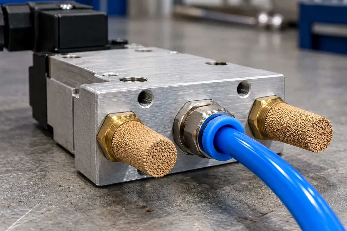
The Festo MHE2-MS1H-3/2G-M7-K (Part number 196133) 3/2-way single-solenoid closed pressure-relief poppet valve has a 10 mm construction width, 100 l/min standard nominal flow rate (DIN 1343), M7 pneumatic working port, 24 V DC operating voltage, and -0.9 bar to 8 bar (-0.09 MPa to 0.8 MPa, -13.05 psi to 116 psi) operating pressure. For the Festo MHE2-MS1H-3/2G-M7-K fast-switching valve, the switching time on is 1.7 ms, switching time off is 2 ms, switching time on/off tolerance is +10%/-30%, switching time dispersion from 1 Hz is 0.2 ms, maximum switching frequency is 330 Hz (100% duty cycle), and 24 V DC coil power is 5.0 W in the high-current phase and 1.25 W in the low-current phase. Across the three Festo MHE fast-switching valve body sizes, the standard M1H coil switching times (on / off) are 7 / 3.5 ms, 8.3 / 4.5 ms, and 10.5 / 5 ms (120 Hz to 130 Hz max switching frequency), whereas the MS1H electronics coil reduces switching times (on / off) to 1.7 / 2 ms (5/2: 1.9 / 1.7 ms), 2.3 / 2.8 ms, and 3.5 / 3.5 ms (330 Hz, 280 Hz, and 210 Hz max frequency).
For larger reject cylinders requiring higher flow rates, compact piloted piston-gate valves can be mounted directly at the actuator port, though shifting time scales upward with nominal bore size. Festo CPE (Compact Performance) solenoid valves (including 5/3-way variants; widths 10, 14, 18, and 24 mm; flow rate 180 to 3200 l/min) are designed for direct mounting on the cylinder or on moving system parts so that short tubing with minimal air volume achieves short switching times, very short reaction times, and shorter machine cycles.
| Valve Architecture Tier | Manifold Application Role | Nominal Size, Flow Rate, and Switching Time Specifications |
|---|---|---|
| Compact piloted piston-gate valve (sub-miniature width) | Direct cylinder or moving-carriage mounting for light reject actuators | For the Festo CPE10 piloted piston-gate solenoid valve (4 mm nominal size, DIN 1343 standard nominal flow rate 190 to 400 l/min and 180 to 350 l/min), switching time on is 14 ms and 16 ms, switching time off is 14 ms and 20 ms, and switching time reversal is 8 ms. |
| Compact piloted piston-gate valve (narrow manifold width) | Close-mounted directional control for medium-bore packaging cylinders | For the Festo CPE14 piloted solenoid valve (6 mm nominal size, DIN 1343 standard nominal flow rate 510 to 900 l/min, 400 to 800 l/min, and 370 to 750 l/min), switching time on is 16 ms, 24 ms, and 20 ms, while switching time off is 27 ms, 32 ms, and 42 ms. |
| Compact piloted piston-gate valve (mid-range manifold width) | High-flow directional control for heavy-duty conveyor diverter arms | For the Festo CPE18 piloted solenoid valve (8 mm nominal size), basic valve switching time on is 28 ms, 26 ms, and 20 ms, switching time off is 18 ms, 20 ms, and 38 ms, and switching time reversal is 13 ms. |
| Compact piloted piston-gate valve (large manifold width) | High-capacity pneumatic actuation for large-bore industrial rams | For the Festo CPE24 piloted solenoid valve (11 mm nominal size, DIN 1343 flow rates from 1,250 to 3,200 l/min), switching time on is 50 ms, 40 ms, and 25 ms, switching time off is 33 ms, 50 ms, and 55 ms, and switching time reversal is 25 ms. |
Electrical coil protection circuits also alter valve release timing on piloted manifolds. Based on dynamic performance test JIS B 8375-1981 (at 0.5 MPa pressure and 20°C coil temperature), SMC SY3000 and SY7000 pilot solenoid valve response times (ms) are specified according to the coil surge voltage suppressor type (Without light/surge voltage suppressor vs Type S, Z vs Type R, U).
| Piloted Valve Manifold Family | Actuation & Coil Protection Scope | Response Time by Coil Surge Suppressor Type |
|---|---|---|
| Standard compact and high-flow piloted manifold valves | Single, double, and three-position directional actuation across suppressor options | At 0.5 MPa, SMC SY3000 response times (Without / Type S, Z / Type R, U) are 12 or less / 15 or less / 12 or less ms (2 position single), 10 or less / 13 or less / 10 or less ms (2 position double), and 15 or less / 20 or less / 16 or less ms (3 position), while SY7000 response times are 31 or less / 38 or less / 33 or less ms (2 position single), 27 or less / 30 or less / 28 or less ms (2 position double), and 50 or less / 56 or less / 50 or less ms (3 position). |
| Mid-range and heavy-duty piloted manifold valves | Single, double, and three-position directional actuation across suppressor options | At 0.5 MPa, SMC SY5000 response times (Without / Type S, Z / Type R, U) are 19 or less / 26 or less / 19 or less ms (2 position single), 18 or less / 22 or less / 18 or less ms (2 position double), and 32 or less / 38 or less / 32 or less ms (3 position), while SY9000 response times are 35 or less / 41 or less / 35 or less ms (2 position single and double) and 62 or less / 64 or less / 62 or less ms (3 position). |
| Intrinsically safe piloted manifold valves | Barrier-protected hazardous-area solenoid actuation | Based on dynamic performance test JIS B 8375-1981 at 70 psi (0.5 MPa), SMC 53-SY5000, 53-SY7000, and 53-SY9000 intrinsically safe solenoid valves have response times of 26 or less, 38 or less, and 50 or less ms for 2-position single actuation, and 22 or less, 30 or less, and 50 or less ms for 2-position double actuation (with default barrier cable parameters Ccable = 60 pF/ft and Lcable = 0.2 µH/ft). |
Tubing Dead Volume and Viscous Pressure Lag Between Valve Manifold and Cylinder
Once the solenoid valve shifts open, compressed air must travel down the connecting line and pressurize the internal volume of the tube before the cylinder piston can reach breakaway pressure. FlowKinetics LLC separates the time lag of pneumatic tubing systems into two physical components: Acoustic lag (where pressure disturbances propagate down the connecting tubing at the speed of sound, taking a finite time interval that is typically small) and Pressure lag (where due to gas viscosity in the tubes, it takes a finite time for the magnitude of the pressure change to register across the volume). Based on the Sinclair and Robins capillary pressure-lag theory (NACA TN 2793, September 1952) cited by FlowKinetics LLC, tubing pressure lag is governed by total system volume (V), tubing length (l), tubing diameter (d), fluid viscosity (μ), and the imposed pressure differential (P1 - Po).
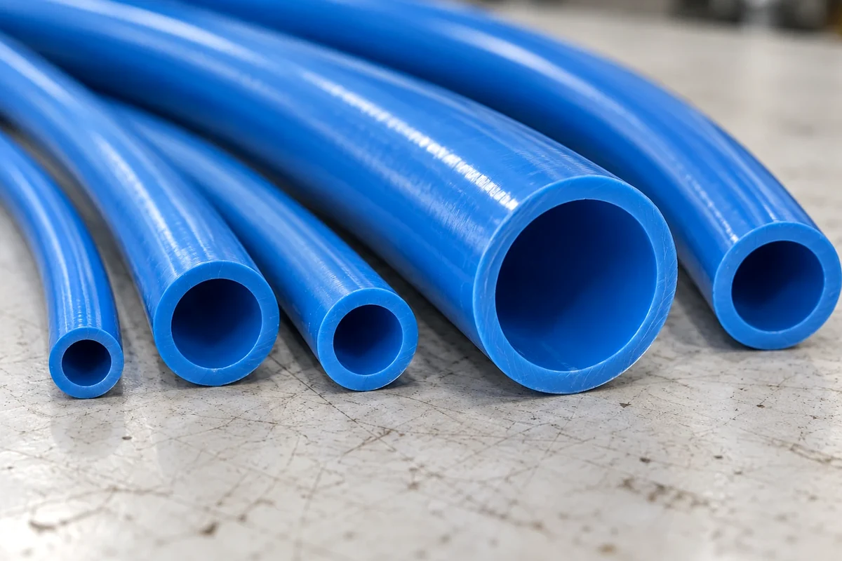
When a centralized valve manifold feeds pairs of 2x1 inch cylinders from 10 feet away using ¼ inch OD tubing with an ID of approximately .180 inch, a single 10-foot tube holds 3.05 cubic inches and the two lines (extend and retract) hold 6.10 cubic inches per complete cycle—over half the 11 cubic inches total volume of the two 5-½ cubic inch cylinders. At 80 psi working pressure, the compression ratio is 6.33, so multiplying by the tubing volume gives a normalized volume of 38.6 standard cubic inches per cycle; actuated five times a minute, filling the tubing for the closest station consumes 193 standard cubic inches per minute (0.11 scfm). Across all four stations in Figure 1 (at tubing lengths of 120, 180, 240, and 300 inches, totaling 840 inches), the two tubing lines hold 42.8 in³ total volume (270.6 standard in³ at compression ratio, or 1353 scim / 0.78 SCFM at 5 cycles per minute), which is almost identical to the 44 in³ total volume of all eight cylinders.
Oversizing the connecting tube to reduce friction loss can backfire on short-stroke actuators because internal dead volume scales with the square of the inside diameter. Replacing ¼ inch tubing with 3/8 inch tubing increases the tubing ID to .27 inches and increases the internal tubing dead volume and annual fill costs by a factor of 2.28 (jumping to $250 per year for one drop-down). On our pneumatic flow control valve sizing guide, on a 32 mm bore, 50 mm stroke cylinder connected via 2.0 m of 8×5.5 mm tubing, the tube holds 47.5 cm³ of air—137% more volume than the 34.6 cm³ rod chamber—cutting pneumatic axial stiffness by 58% and degrading velocity repeatability by 25% to 50%. On our pneumatic tubing inside diameter sizing guide, SMC TU tubing models have outside/inside diameters of 6 mm OD / 4 mm ID (TU0604), 8 mm OD / 5 mm ID (TU0805), 10 mm OD / 6.5 mm ID (TU1065), and 12 mm OD / 8 mm ID (TU1208), while SMC TUH Standard Type tubing models have 6 mm OD / 4.4 mm ID (TUH0644) and 8 mm OD / 5.8 mm ID (TUH0858).
At the same time, excessive tubing length chokes peak mass flow during the stroke. Pneumatic component flow capacity is expressed as a unitless Cv or effective area S in mm², and the longer the tubing or pipe, the lower the flow capacity: each 4-fold increase in length reduces the flow capacity by 1/2.
Close-Mounted Valve Manifolds and Quick Exhaust Valves for Reject Actuator Speed
Eliminating remote manifold runs converts parasitic line volume into usable actuator thrust and sharpens reject timing repeatability. Mounting directional control valves on or near the actuators—supplied by a continuous pressure line that acts as favorable energy capacitance—leaves electrical response times unaffected while pneumatic response times improve dramatically. Reduce circuit volume that compromises performance by mounting directional valves as close as possible to cylinders, rotary actuators, or other end effectors, while ensuring sufficient flow capacity in connectors and tubing.
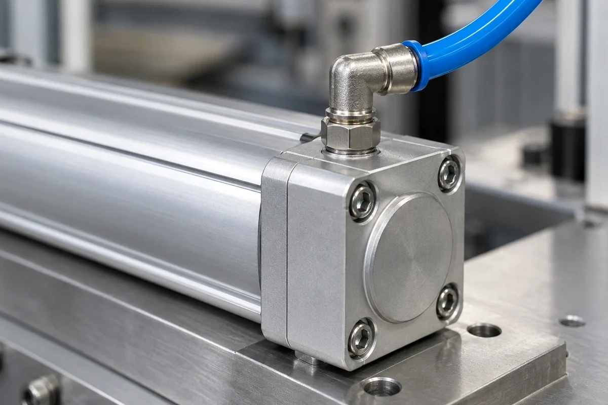
When the directional valve cannot be mounted directly on the cylinder port, threading a quick exhaust valve directly into the cylinder port dumps exhaust air to atmosphere locally rather than forcing it back through the connecting tube and solenoid exhaust gallery. In an assembly machine pneumatic valve retrofit reported in Compressed Air Best Practices, laboratory testing with a 6.4 gallon tank compressed to 85 psig and six feet of tubing set to 45 psi return pressure showed that adding ASR/ASQ pressure-saving and quick-exhaust components yielded 54 strokes from the tank (an increase of 7 versus the 47-stroke baseline).
| Quick Exhaust Component Aspect | Circuit Installation Role | Sonic Conductance and Operating Precaution Specifications |
|---|---|---|
| Threaded inline quick exhaust valve flow capacity | Direct port mounting at the reject cylinder cap or rod end | SMC Series AQ threaded quick exhaust valves provide sonic conductance C [dm3/(s·bar)] from IN to OUT and OUT to EXH of 0.4 and 0.56 on AQ1500-M5 (M5 x 0.8), 0.8 and 1.16 on AQ1510-01, 5 and 5 on AQ2000-01, 7 and 8 on AQ2000-02, 8 and 8.4 on AQ3000-02, and 12 and 14 on AQ3000-03. |
| Quick exhaust shuttle operating precautions | Upstream solenoid valve and supply line effective-area matching | SMC Series AQ quick exhaust valve precautions warn that air may not be sufficiently exhausted under three conditions: (a) with residual pressure or back pressure on the IN side, (b) when the differential pressure between the IN and OUT sides is smaller than the minimum operating pressure, or (c) when the effective area of the IN-side piping or solenoid valve is smaller than the AQ valve. |
Calculating Total Reject Cylinder Cycle Time, Force Margin, and Peak Air Flow Demand
Once the valve shifting delay and tubing fill lag are cleared, the cylinder piston must accelerate the reject shoe across the stroke window before the container exits the reject zone. AutomationDirect states that reliably moving a load at high speeds may require a cylinder force that exceeds the load by 50% or more: at 100 psi supply pressure, available piston pressure is reduced to no less than 90 psi on a slow-moving load, but can drop as low as 70 psi when moving at a fast rate.
To size the upstream regulator, main supply header, and directional valve sonic conductance so that inlet pressure drop stays within standard limits during rapid actuation, engineers must evaluate instantaneous peak flow rather than time-averaged compressor consumption. Flodraulic Group gives the standard pneumatic formulas: Compression Ratio = (psig + 14.7) / 14.7, Consumption (cu ft) = Area (in²) x Stroke (ins) x compression ratio / 1,728, Air Demand (scfm) = 60 x Area (in²) x piston speed x compression ratio / 1,728, and Peak Air Flow (Q) = volume / time x compression ratio. In FOKCA Automation test measurements on a Ø32mm cylinder (804 mm² piston area) across a 160mm effective stroke window (from 20mm to 180mm), PLC magnetic-switch timing recorded 0.325 s for an actual speed of 492mm/s, while flow monitoring recorded 105 L/min average instantaneous flow rate (corresponding to 520 mm/s theoretical speed).
High-Speed Reject Ram Timing and Tubing Delay Commissioning Checklist
Before locking the PLC encoder shift-register delay on a high-speed reject conveyor, verify each physical parameter below on the machine:
- Sensor-to-reject conveyor distance and pitch count: Measure the linear distance from the optical inspection trigger to the centerline of the reject ram face, divide by container pitch, and record belt speed to determine the available actuation window in milliseconds.
- Solenoid valve nominal shifting time and coil circuit: Record both the catalog shifting on-time and shifting off-time in milliseconds for the installed valve series, and verify whether a flyback diode or surge voltage suppressor module is installed on the coil terminals.
- Manifold-to-cylinder tubing length and inside diameter: Measure the exact polyurethane tubing length and inside diameter on both the extend and retract ports, and calculate whether the connecting line internal volume exceeds the cylinder chamber volume.
- Upstream supply reservoir and port pressure stability: Confirm that the air supply line feeding the valve manifold maintains pressure drop within standard test limits during peak stroke flow so pilot-operated spools do not experience sluggish shifting.
- Local exhaust path and cylinder force margin: Verify that high-speed reject cylinders carry sufficient force margin for dynamic pressure drop and use close-mounted directional valves or port-mounted quick exhaust valves with properly matched upstream effective area.
Sources
- International Organization for Standardization, Pneumatic Fluid Power Directional Control Valves Measurement of Shifting Time (ISO 12238 and ISO 6358-1 and ISO 80000-1).
- Venkataraman et al., Experimental Investigation on Response Time of Pneumatic Direct Acting Solenoid Valve, Engineering, Technology and Applied Science Research.
- Clark Cooper, Direct-Acting vs. Pilot-Operated Solenoid Valves Operating Principles and Pressure Differential Requirements.
- Festo SE & Co. KG, Solenoid Valve MHE2-MS1H-3/2G-M7-K Technical Data Sheet and Fast-Switching Valves Catalog Specifications (M1H and MS1H coils, DIN 1343).
- Festo SE & Co. KG, Solenoid Valves CPE Compact Performance Technical Catalog, DIN 1343 Flow and Switching Time Specifications.
- SMC Corporation, Series SY3000 and SY7000 and 53-SY5000, 53-SY7000, and 53-SY9000 Solenoid Valve Catalog Specifications (JIS B 8375-1981 Dynamic Performance Test).
- Power & Motion Tech, Five-Port Solenoid Valves Product Specification Summary.
- FlowKinetics LLC, Time Lag of Pressure Systems Application Note (citing Sinclair and Robins, Method for the Determination of the Time Lag in Pressure Measuring Systems Incorporating Capillaries, NACA TN 2793, September 1952).
- SMC Corporation, Inconsequential Volume Tubing Dead Volume and SCFM Consumption Analysis and Pneumatics in Machine Design Engineering Guides.
- Compressed Air Best Practices, Assembly Machine Pneumatic Valve Retrofit Laboratory Testing.
- SMC Corporation, Series AQ Quick Exhaust Valve Catalog (AQ1500-M5, AQ1510-01, AQ2000-01, AQ2000-02, AQ3000-02, and AQ3000-03 Sonic Conductance and Operating Precautions).
- AutomationDirect, Pneumatic Cylinder Speed Engineering Guide.
- Flodraulic Group, Basic Pneumatic Formulas for Compression Ratio, Consumption, Air Demand, and Peak Air Flow.
- FOKCA Automation, Experimental Cylinder Speed Measurement and Instantaneous Flow Analysis on Pneumatic Cylinders.