Start pneumatic tubing pressure-drop sizing with the cylinder’s stroke demand and the selected tube’s inside diameter. The flow rate required for a single stroke often controls valve and piping size.
Determining maximum cylinder speed requires all flow losses, force-output pressure and available inlet pressure.
Use this guide to assemble the sizing inputs, compare tubing dimensions, and review the valve-to-actuator route. For the wider air system, visit our compressed-air guides.
Establish the actuator pressure-drop limit
Know the recommended operating pressure for each piece of pneumatic equipment.
Cylinder output force depends on air pressure.
Higher speeds cause greater pressure loss because air flows faster through valves, tubing and ports.
Put the available inlet pressure, required actuator pressure, and flow losses beside each other in the sizing record. Evaluate the proposed tube and fittings against that application requirement.
Most well-designed air systems have no more than 10% pressure drop between compressor and point of use.
Apply that benchmark to the compressor-to-use system. For the cylinder branch, return to the equipment’s operating-pressure requirement and the complete flow-loss review.
Calculate flow during the stroke
For momentary single-stroke flow sizing, begin with the single-stroke calculation. Enter the stroke duration and displacement for the movement under review.
SCFM inst = (C x Dp x S x 60) / T
T is the time for one stroke in seconds.
Dp is cylinder displacement in ft³ per inch of stroke.
S is stroke length in inches.
C = (Supply pressure (psig) + 14.7) / 14.7
Keep an average-consumption calculation alongside the stroke calculation:
SCFM avg = C x Dp x S x SPM
SPM = Strokes per minute, count both in and out strokes
Record the single-stroke result and average-consumption result separately. Carry the stroke-flow requirement forward to the tubing and valve review.
Confirm tubing inside diameter by model
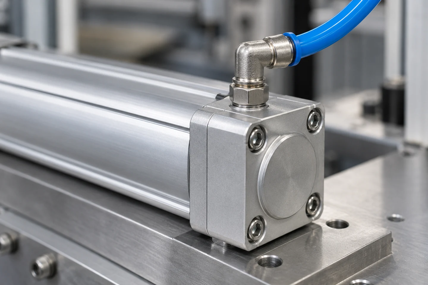
Outside diameter drives matching tubing to a push lock or other fitting.
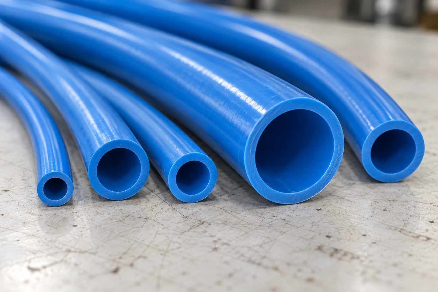
Tubing wall thickness affects inside diameter; thicker walls reduce ID and air flow.
Compare the dimensions below when reviewing polyurethane air tubing. Keep the manufacturer and series with each candidate in your sizing record.
| Series | Outside diameter | Inside diameter |
|---|---|---|
| SMC TU | TU0604 has outside diameter 6 mm. | TU0604 has inside diameter 4 mm. |
| SMC TU | TU0805 has outside diameter 8 mm. | TU0805 has inside diameter 5 mm. |
| SMC TU | TU1065 has outside diameter 10 mm. | TU1065 has inside diameter 6.5 mm. |
| SMC TU | TU1208 has outside diameter 12 mm. | TU1208 has inside diameter 8 mm. |
| SMC TUH Standard Type | TUH0644 has outside diameter 6 mm. | TUH0644 has inside diameter 4.4 mm. |
| SMC TUH Standard Type | TUH0858 has outside diameter 8 mm. | TUH0858 has inside diameter 5.8 mm. |
Include the installed bend
PUN-H-6X1-TBL has flow-relevant bending radius 26 mm.
PUN-H-6X1-TBL has minimum bending radius 10 mm.
Record both bend-radius fields under the exact Festo tubing model when checking a proposed route.
Check push-to-connect fitting restrictions
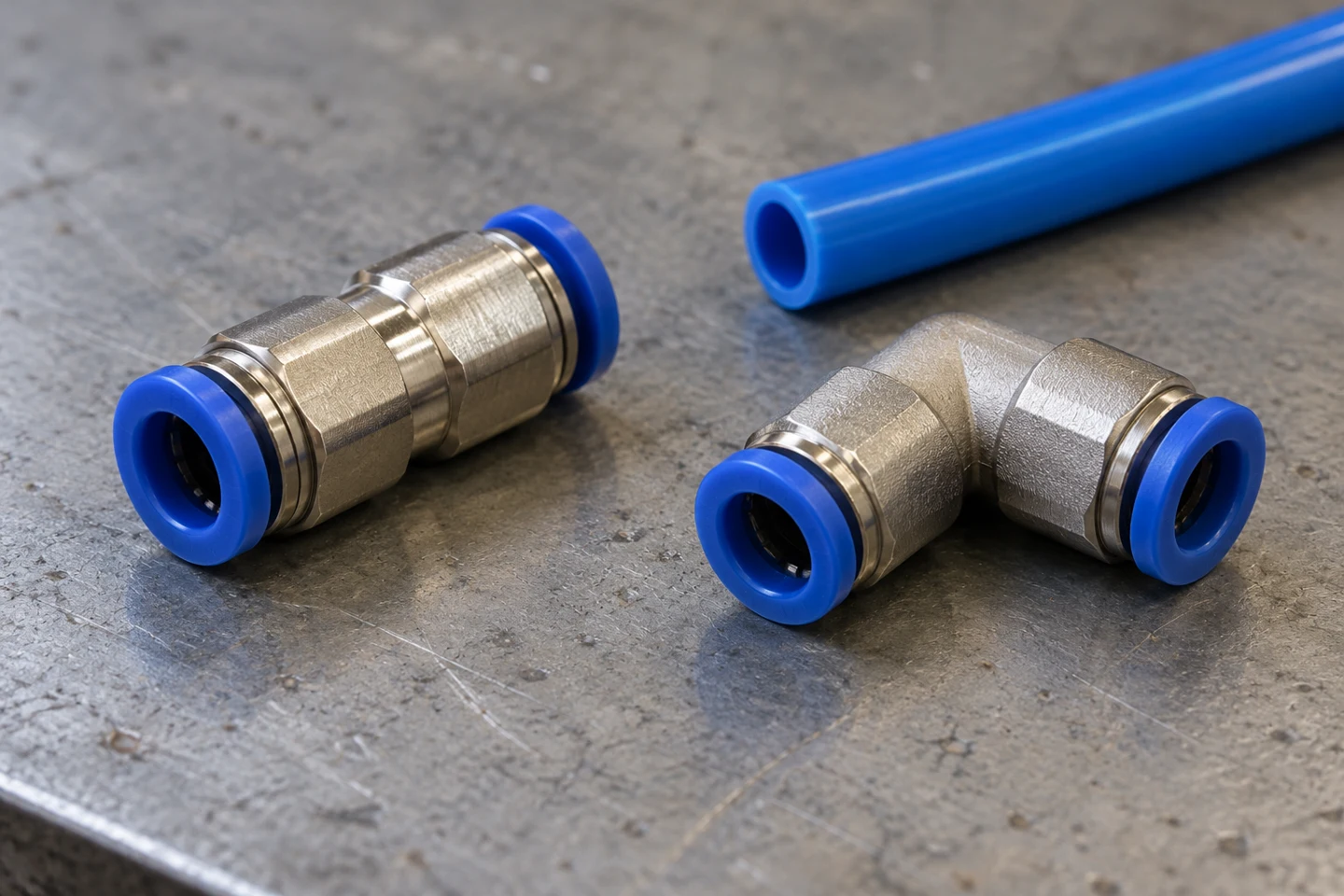
Flow around bends and restrictions in valves and fittings cause pressure losses.
Check valve flow rate rather than relying solely on port size.
Use the fitting’s flow data in the component review. Review the SMC catalogue entries below for each specified tubing material.
| Fitting entry | Nylon tubing | Urethane tubing |
|---|---|---|
| Straight union | KQ2H08-00A effective area with nylon tubing is 26.1 mm2. | KQ2H08-00A effective area with urethane tubing is 18 mm2. |
| Union elbow | KQ2L08-00A effective area with nylon tubing is 21.6 mm2. | KQ2L08-00A effective area with urethane tubing is 14.9 mm2. |
Review line length and nominal flow
Increasing supply tubing size while minimizing necessary length is a pressure-drop reduction method.
Festo’s nominal-flow calculation takes inlet pressure, outlet pressure, tube length and internal diameter.
Enter those values for the selected tubing. Keep the calculation inputs and result with the component record, then review the valves and fittings along the same route.
Sizing record to complete
- Cylinder movement and stroke length
- Cylinder displacement and stroke duration
- Required actuator operating pressure
- Available branch inlet pressure
- Tube manufacturer, series, outside diameter, and inside diameter
- Installed tube length and bend details
- Fitting types, quantity, and material-specific flow data
- Valve flow data
- Single-stroke flow calculation
- Nominal-flow calculation inputs and result
Use this record to review the proposed assembly before final selection. Continue with air preparation for packaging lines for the upstream equipment review.
Common sizing questions
Can tube size affect cylinder speed?
Actuator speed can also be affected by port and tubing sizes.
Should I review cylinder exhaust flow too?
Controlling flow at the actuator exhaust port is the most common industry practice for controlling speed.
What should I change when reviewing an unnecessarily long supply tube?
Increasing supply tubing size while minimizing necessary length is a pressure-drop reduction method.
Sources
- Bosch Rexroth — The Use and Application of Air Cylinders and Valves
- AutomationDirect — Pneumatics In Depth: Cylinder Speed
- CAGI — Technical Brief on Pressure Drop
- SMC USA — Control Air Flow of Cylinders
- AutomationDirect — How to Specify Pneumatic Tubing & Fittings
- SMC — Polyurethane Tubing TU/TIUB
- SMC — Tubing catalogue T/TU/TUH
- Festo — PUN-H tubing technical datasheet
- SMC — One-touch Fittings
- Festo — Flow rate calculation