
Selecting a compressed air dryer requires matching the middle digit of the ISO 8573-1:2010 [particles:water:oil] purity specification—the required Pressure Dew Point (PDP) at full line pressure—against the lowest ambient temperature the distribution piping encounters and the moisture tolerance of the packaging process. Installing an undersized refrigerated dryer or running an unmaintained desiccant bed allows liquid condensate or abrasive desiccant dust to enter the header, which washes factory grease out of pneumatic cylinders, causes lapped-spool directional solenoid valves to stick, contaminates open food containers, or wastes 14% to 18% of compressor output in unnecessary purge air.
While our parent note on air preparation questions for a packaging line sets out the overall three-part ISO 8573-1:2010 notation, the Class 0 boundary rule, and point-of-use sampling after flexible hoses inside the compressed air section, this engineering guide focuses on the water class digit (Classes 1 through 6) and the thermodynamic sizing of refrigerated vs. desiccant air dryers, hollow-fiber membrane dryers, CAGI ADF 100 inlet temperature correction factors, and mandatory coalescing filter trains.
| Dryer Technology | ISO 8573-1 Water Class & Outlet PDP | Compressed Air Purge Loss (%) | Specific Package Power (kW / 100 scfm) |
Typical Pressure Drop (ΔP) |
Mandatory Companion Filtration | Primary Packaging & Plant Application |
|---|---|---|---|---|---|---|
| Non-Cycling Refrigerated Dryer (Hot-Gas Bypass) | Class 4: ≤ +3 °C (+37.4 °F; 35–39 °F nominal) |
0% (with zero-loss electronic level drain) | ~0.79 kW (constant at part load) |
3–5 psid (0.2–0.35 bar) |
Wet separator + 1.0 µm general-purpose pre-filter |
Steady-load indoor packaging halls (> +10 °C ambient) running [2:4:2] indirect pneumatic actuators |
| Cycling / Thermal-Mass / VSD Refrigerated Dryer | Class 4: ≤ +3 °C (+37.4 °F) |
0% (with zero-loss electronic level drain) | ~0.60–0.80 kW (scales down with air demand) |
3–5 psid (0.2–0.35 bar) |
Wet separator + 1.0 µm pre-filter (+ 0.01 µm for [1:4:2]) |
Multi-shift packaging lines with variable shift demand; case erectors, palletizers, and ISO 15552 cylinders |
Heatless Regenerative Desiccant Dryer (PSA) |
Class 2: ≤ -40 °C (-40 °F) or Class 1: ≤ -70 °C (-94 °F) |
14% to 18% (15% nominal across orifice) |
~3.0–3.8 kW (dominated by purge air shaft power) |
3–5 psid (dryer) + 3–6 psid (filters) |
Wet separator + 1.0 µm pre-filter + 0.01 µm coalescer + 1.0 µm dust after-filter |
Point-of-use direct food blow-off [2:2:1], sub-freezing outdoor headers, or small aseptic drops (< 150 scfm) |
| Externally / Internally Heated Desiccant Dryer | Class 2: ≤ -40 °C (-40 °F) or Class 1: ≤ -70 °C (-94 °F) |
6% to 8% average purge air | ~2.0–2.6 kW (electric heater + reduced purge) |
3–5 psid (dryer) + 3–6 psid (filters) |
Same 4-stage coalescing & high-temperature dust after-filter train | Medium central headers (150–400 scfm) requiring -40 °C PDP with moderate compressor reserve |
| Heated Blower Purge Desiccant Dryer (Zero-Purge) | Class 2: ≤ -40 °C (-40 °F) or Class 1: ≤ -70 °C (-94 °F) |
0% to 2% (0% with closed-loop cooling) |
~1.2–1.8 kW (lowest OpEx with dew-point switching) |
3–5 psid (dryer) + 3–6 psid (filters) |
Same 4-stage coalescing & high-temperature dust after-filter train | Large food, beverage, and pharmaceutical central headers (≥ 300–500 scfm) where compressor air cannot be wasted |
Heat-of-Compression (HOC) Desiccant Dryer |
Class 2: ≤ -40 °C (-40 °F) or Class 3: ≤ -20 °C |
0% net purge loss | ~0.80 kW (U.S. DOE Sourcebook, p. 50) |
2–4 psid |
Particulate after-filter (oil-free compressor discharge only) | Restricted to centrifugal or lubricant-free rotary screw compressors with ≥ 300 °F discharge air |
| Hollow-Fiber Membrane Dryer (Point-of-Use) | Class 3 to 4: -20 °C to +3 °C (down to -40 °C at high sweep) |
10% to 20% continuous sweep gas | ~3.0–4.0 kW eq. (0 W electrical connection) |
2–5 psid |
Wet separator + 1.0 µm pre-filter + 0.01 µm coalescer upstream |
Cold-storage rooms (+4 °C to -15 °C), ATEX / NEC Class I, Div 1 explosion-proof zones, single-drop polishing |
1. ISO 8573-1:2010 Water Purity Classes (Classes 1–6) and Packaging Line Targets
As Ruby Ochoa (President of Trace Analytics) explains in Compressed Air Best Practices: Using ISO 8573-1 to Test Compressed Air, ISO 8573-1:2010 writes compressed air purity as [A:B:C], where A is solid particles (Classes 0–7, X), B is humidity and liquid water (Classes 0–9, X), and C is total oil across aerosol, liquid, and vapor (Classes 0–4, X). For the water digit (B), Classes 1 through 6 are defined by maximum allowable Pressure Dew Point (PDP)—the temperature at which water vapor begins to condense into liquid while the air is held at full operating line pressure (referenced at 7 bar(g) / 100 psig and corrected to 20 °C, 1 bar(a) reference volume). Once liquid water is present in the stream, the air is already 100% saturated and falls into Classes 7, 8, 9, or X, which are graded by liquid water mass concentration (C_w in g/m³).
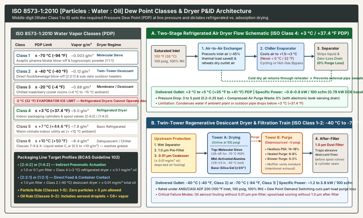
Complete ISO 8573-1:2010 Humidity and Liquid Water Class Lookup Table
| ISO 8573-1 Water Class | Maximum Pressure Dew Point (°C) |
Maximum Pressure Dew Point (°F) |
Residual Water Vapor or Liquid (g/m³) |
Required Dryer Architecture | Packaging & Industrial Line Boundary |
|---|---|---|---|---|---|
| Class 0 | User/supplier specified (< -70 °C) |
< -94 °F (explicit limit required) |
< 0.003 g/m³ vapor |
Multi-bed molecular sieve with dew-point lock | Must write explicit limit in parentheses, e.g. [1:0 (-80 °C):1]; class 0 never means zero moisture |
| Class 1 | ≤ -70 °C |
≤ -94 °F |
~0.003 g/m³ vapor |
Twin-tower regenerative desiccant with 3Å–4Å molecular sieve polishing layer |
Moisture-reactive pharmaceutical blister/vial blow-off, hygroscopic effervescent powder conveying ([1:1:1]) |
| Class 2 | ≤ -40 °C |
≤ -40 °F |
~0.12 g/m³ vapor |
Twin-tower regenerative desiccant (activated alumina / silica gel) or low-PDP membrane |
Direct food & beverage contact (BCAS Guideline 102 [2:2:1] / [1:2:1]): air knives, container rinsing, bag opening, and outdoor winter headers |
| Class 3 | ≤ -20 °C |
≤ -4 °F |
~0.88 g/m³ vapor |
Point-of-use hollow-fiber membrane dryer or dew-point-switched desiccant dryer (-20 °C setpoint) |
Chilled food, meat, dairy, and produce packaging rooms (+4 °C to -15 °C ambient) where a +3 °C refrigerated dryer condenses in the drop leg |
| Class 4 | ≤ +3 °C |
≤ +37.4 °F (35–39 °F field spec) |
~6.0 g/m³ vapor |
Standard refrigerated air dryer (cycling thermal-mass, VSD, or non-cycling) | Indirect contact / general indoor automation (BCAS Guideline 102 [2:4:2] or [1:4:2]): indoor plants > +10 °C feeding cylinders and directional valves |
| Class 5 | ≤ +7 °C |
≤ +44.6 °F |
~7.8 g/m³ vapor |
High-PDP refrigerated dryer or membrane dryer | Basic indoor shop air in warm facilities where ambient temperature permanently stays above +17 °C (63 °F) |
| Class 6 | ≤ +10 °C |
≤ +50 °F |
~9.4 g/m³ vapor |
Chilled-water aftercooler or single-tower deliquescent salt dryer (15–50 °F suppression) |
Rough utility air; unsuitable for high-cycle packaging solenoid manifolds |
| Classes 7–9 & X | Saturated (100% RH) |
Saturated (100% RH) |
Liquid C_w: Class 7 ≤ 0.5; Class 8 ≤ 5; Class 9 ≤ 10; Class X > 10 g/m³ |
Compressor aftercooler and mechanical moisture separator only (no dryer) | Liquid water slugs wash out factory cylinder grease and corrode spool valves |
Matching Multi-Class Packaging Targets ([2:4:2] vs. [2:2:1])
In food, beverage, and consumer-goods packaging plants, Ochoa cites the British Compressed Air Society (BCAS) Food and Beverage Grade Compressed Air Best Practice Guideline 102 (tested at least twice a year and after maintenance) to separate plant drops into two distinct moisture and filtration tiers:
- Indirect Contact & General Pneumatic Actuation (
ISO 8573-1:2010 [2:4:2]or[1:4:2]): Air that drivesISO 15552profile cylinders,ISO 21287compact cylinders, case erectors, and high-speed reject rams inside a heated factory hall (> +10 °C / 50 °F) and exhausts away from open product requires Water Class 4 (≤ +3 °C / +37.4 °FPDP). Because a+3 °Cpressure dew point sits at least7 °C to 15 °Cbelow indoor room temperature, water vapor stays in the gas phase through the manifold and directional valves. Remember Ochoa’s easily missed particle rule: for Particle Classes 1 through 5, zero particles larger than5 µmare permitted. - Direct Product or Packaging Surface Contact (
ISO 8573-1:2010 [2:2:1]or[1:2:1]): Air that touches food, blows out glass jars or PET preforms, opens flexible pouches, or contacts food-contact conveyor surfaces must meet Water Class 2 (≤ -40 °C / -40 °FPDP) alongside Oil Class 1 (≤ 0.01 mg/m³total liquid, aerosol, and vapor). Lowering the pressure dew point to-40 °Creduces residual water vapor from~6.0 g/m³down to~0.12 g/m³—a 98% reduction in water vapor mass—inhibiting microbial growth inside distribution piping where ambient moisture would otherwise support bacteria and mold spores.
2. Refrigerated Compressed Air Dryers: Two-Stage Heat Exchange, the 0 °C Ice Barrier, and CAGI ADF 100 Derating
For indoor packaging machinery operating above +10 °C (50 °F), the refrigerated compressed air dryer is the primary workhorse because it consumes zero compressed air for purge and operates at ~0.6 to 0.8 kW per 100 scfm (U.S. Department of Energy / Compressed Air Challenge Sourcebook, pages 11–12 and 49).
How Two-Stage Precooling/Reheating and the Evaporator Work
Per the U.S. DOE Sourcebook (page 11), an industrial refrigerated dryer passes warm, saturated compressed air through two sequential heat exchangers:
- Stage 1 — Air-to-Air Heat Exchanger (Precooler / Reheater): Incoming
100 °F(38 °C) saturated air exchanges heat counter-currently with the cold+3 °C(+37.4 °F) dry air leaving the separator. This stage precools the incoming air—removing 40% to 50% of the heat load before the refrigerant circuit—while simultaneously reheating the outgoing dry air to roughly75 °F to 85 °F(24 °C to 29 °C). Reheating the outlet stream prevents humid factory-hall air from condensing (“sweating”) on the outside of downstream overhead air headers. - Stage 2 — Refrigerant-to-Air Evaporator & Mechanical Separator: A closed-loop refrigeration system chills the precooled air to
+1.5 °C to +3 °C(+35 °F to +37.4 °F). Condensed liquid water droplets are stripped by a centrifugal or coalescing mechanical separator and discharged through an automatic condensate drain. - The
0 °C(32 °F) Evaporator Freezing Limit: Because moisture is removed as liquid water, the evaporator surface temperature must never drop below0 °C(32 °F). If the refrigerant suction temperature falls below freezing, condensed water freezes into solid ice inside the heat-exchanger channels, blocking airflow and splitting copper or stainless-steel exchanger plates. Consequently, no refrigerated dryer can deliver anISO 8573-1Water Class 1, 2, or 3 sub-freezing dew point.
Non-Cycling (Hot-Gas Bypass) vs. Cycling (Thermal-Mass / VSD) Designs
- Non-Cycling Refrigerated Dryers: The refrigerant compressor runs continuously at 100% speed regardless of how many packaging lines are running. When compressed-air flow drops on night shifts or changeovers, a hot-gas bypass valve injects hot refrigerant discharge gas directly into the evaporator suction side to keep the coil from freezing below
32 °F. While simple and lower in purchase price, a non-cycling unit draws nearly 100% of its full-load electrical kW even at 10% compressed-air flow. - Cycling (Thermal-Mass and Variable-Speed Drive) Dryers: A thermal-mass cycling dryer cools an intermediate thermal storage medium (such as a glycol/water bath, aluminum block, or phase-change material), allowing a thermostat to shut off the refrigerant compressor entirely during low airflow or cool winter ambient conditions. Larger units use a Variable-Speed Drive (
VSD) refrigerant compressor. OnCAGI Form REF 010data sheets (CAGI Standard for Rating and Testing of Refrigerated Compressed Air Dryers), comparing Total Dryer Input Power at 100% Flow vs. 10% Flow immediately shows how much part-load electricity a cycling dryer saves. - Zero-Loss Electronic Level-Sensing Drains vs. Timer Solenoid Drains: A timer-operated solenoid drain opens for a fixed number of seconds every few minutes, blowing compressed air to atmosphere once the liquid clears. Specifying a zero-loss electronic level-sensing drain keeps compressed-air purge loss at 0% and eliminates false ultrasonic hits during a plant compressed-air leak survey or quantitative ultrasonic compressed air leak detection walk.
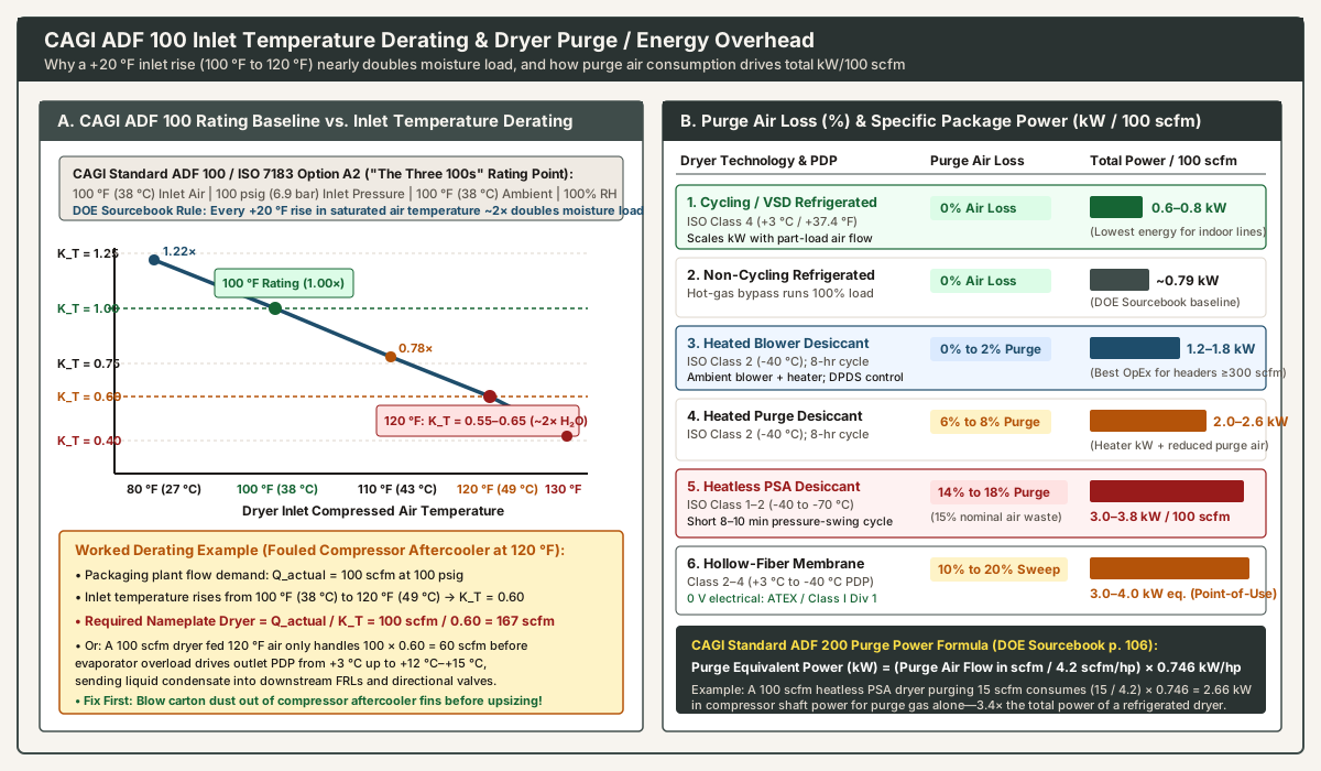
CAGI Standard ADF 100 (“The Three 100s”) and the 120 °F Inlet Temperature Trap
Per CAGI Standard ADF 100 / Data Sheet Form REF 010 (conforming to ISO 7183 Table 2 Option A2 and reproduced in Appendix C of the U.S. DOE Sourcebook, page 105), every refrigerated compressed air dryer’s nameplate flow (scfm referenced to 14.5 psia, 68 °F / 20 °C, and 0% RH) is rated at “the three 100s”:
- Inlet Compressed Air Temperature:
100 °F(38 °C/37.78 °C), saturated (100% RH) - Inlet Compressed Air Pressure:
100 psig(6.9–7.0 bar) - Maximum Ambient Air Temperature:
100 °F(38 °C)
The most common root cause of water carryover past a refrigerated dryer in a packaging plant is elevated inlet air temperature caused by corrugated-carton dust, stretch-film lint, or poor ventilation fouling the air compressor’s built-in aftercooler. The U.S. DOE Sourcebook (page 11) states the governing thermodynamic rule of thumb: reducing the temperature of saturated compressed air by 20 °F reduces its moisture content by approximately 50%. Conversely, when a fouled compressor aftercooler lets dryer inlet temperature climb by 20 °F—from the 100 °F (38 °C) CAGI ADF 100 rating baseline up to 120 °F (49 °C)—the mass of water vapor entering the dryer nearly doubles.
Because the dryer’s refrigeration circuit must remove nearly twice the latent heat of condensation plus additional sensible heat, its effective flow capacity drops by 35% to 45% (an inlet temperature correction factor of K_T = 0.55 to 0.65 at 120 °F):
- Conditional Sizing Equation:
Q_rated = Q_actual / (K_T × K_P × K_A) - Worked Calculation Example: Suppose a packaging plant requires
Q_actual = 100 scfmat100 psig(K_P = 1.00) and100 °Fambient (K_A = 1.00), but compressor discharge air enters the dryer at120 °F(49 °C), where a typical manufacturer inlet correction factor isK_T = 0.60. To hold a+3 °C(+37.4 °F) Class 4 outlet dew point under that thermal load, the required nameplate dryer capacity isQ_rated = 100 scfm / 0.60 = 167 scfm. Conversely, if a100 scfmnameplate dryer is fed100 scfmat120 °F, its effective capacity is only100 × 0.60 = 60 scfm; the overloaded evaporator allows outlet pressure dew point to climb into the+12 °C to +16 °C(54 °F to 61 °F) range, condensing liquid water inside70 °Fplant headers. Before buying an oversized167 scfmdryer, blow out the compressor aftercooler fins and verify that aftercooler approach temperature stays within15 °F to 20 °Fabove ambient.
3. Twin-Tower Regenerative Desiccant and Point-of-Use Membrane Dryers
Whenever compressed air piping runs outdoors through winter frost, enters a chilled food cooler (+4 °C to -15 °C), or contacts food, beverage containers, or hygroscopic pharmaceuticals (ISO 8573-1 Water Classes 1, 2, or 3), a refrigerated dryer cannot prevent condensation. Sub-freezing pressure dew points require adsorption drying (twin-tower regenerative desiccant) or selective permeation (hollow-fiber membrane).
Twin-Tower Desiccant Bed Stratification: Silica Gel, Activated Alumina, and Molecular Sieve
Rated under ANSI/CAGI Standard ADF 200 (100 °F inlet air, 100 psig, 100% RH; U.S. DOE Sourcebook, pages 12, 50, and 106), a regenerative desiccant dryer alternates compressed air between two pressure vessels: Tower A adsorbs water vapor onto microscopic internal pores at full line pressure while Tower B is depressurized to near atmospheric pressure and regenerated. Per the U.S. DOE Sourcebook (page 12), industrial desiccant beds frequently stratify three solid adsorbents by height:
- Water-Resistant Silica Gel Buffer Zone (
≥ 1/4 in.beads at the wet inlet base,15%–20%of bed): Absorbs accidental liquid water carry-over without hydrothermal shattering, shielding the main bed from liquid slugs. - Activated Alumina (
1/8 in. to 1/4 in.porousAl₂O₃beads, main bulk bed): Provides high mechanical crush strength during pressure swings and reliably dries compressed air down to ISO Class 2 (-40 °C / -40 °FPDP). - Molecular Sieve (
3Å to 4Åsynthetic crystalline aluminosilicate zeolites, top outlet polishing layer): Retains strong affinity for water vapor even at ultra-low partial pressures and elevated inlet temperatures, achieving ISO Class 1 (-70 °C / -94 °FPDP).
Do not confuse regenerative adsorption dryers with single-vessel deliquescent chemical dryers (U.S. DOE Sourcebook, pages 12 and 49). Deliquescent dryers use hygroscopic salt tablets (calcium, sodium, potassium, or urea) that dissolve into corrosive liquid brine as they absorb moisture, suppress dew point by only 15 °F to 50 °F below inlet temperature, and risk corrosive salt mist carryover into downstream aluminum valve bodies.
Comparing the Four Desiccant Regeneration Architectures (14–18% vs. 0–2% Purge)
The dominant lifecycle cost of a twin-tower desiccant dryer is not electrical control power—it is the compressed air consumed during tower regeneration. Appendix C of the U.S. DOE Sourcebook (page 106, CAGI Standard ADF 200 Regenerative Desiccant Dryer Data Sheet) converts compressed-air purge flow (Q_purge in scfm) directly into equivalent compressor shaft power (P_purge in kW) at 4.2 scfm per horsepower:
- CAGI ADF 200 Purge Power Equation:
P_purge (kW) = (Q_purge / 4.2) × 0.746 - Heatless Regenerative (
PSA/ Pressure Swing Adsorption) —14% to 18%Purge Loss (~15%nominal): Operates on a rapid8-to-10 minuteNEMA cycle (4–5 minutesdrying per tower). A fixed orifice expands14% to 18%of the dried outlet air to atmospheric pressure through the offline bed to strip adsorbed moisture without heaters. On a100 scfmheatless dryer purging15 scfm, purge air alone consumes(15 / 4.2) × 0.746 = 2.66 kWof compressor power; adding pressure drop and controls brings total specific power to~3.0 to 3.8 kW per 100 scfm, leaving only82 to 86 scfmfor the packaging floor. - Externally or Internally Heated Purge Desiccant —
6% to 8%Purge Loss: Runs on an8-hourNEMA cycle (4 hoursdrying per tower). Electric resistance heaters warm a smaller stream of expanded dry purge air to300 °F–375 °F(149 °C–190 °C) for~3 hours, followed by~1 hourof unheated cool-down purge, cutting compressed-air loss in half (~2.0 to 2.6 kW/100 scfmcombined heater and purge power). - Heated Blower Purge Desiccant (with Zero-Purge Cooling) —
0% to 2%Purge Loss: An external centrifugal blower pushes ambient room air across an electric heater through the regenerating tower, consuming 0% compressed air during heating. Standard blower-purge units use~2%dried compressed air during cool-down, while closed-loop zero-purge designs recirculate cooled air with a heat exchanger to preserve 100% of compressor output (~1.2 to 1.8 kW/100 scfm). - Dew Point Demand Switching (
DPDS): Fixed-timer desiccant dryers purge at full design rate even when a packaging line runs at 40% capacity or cool winter inlet temperatures. Adding an inline capacitive hygrometer holds the online tower in service until the outlet dew point actually rises toward-40 °C, extending cycle times and cutting purge or heater energy in proportion to real moisture load (U.S. DOE Sourcebook, page 12).
Point-of-Use Hollow-Fiber Membrane Dryers and Class I, Division 1 Hazardous Zones
A hollow-fiber membrane dryer (U.S. DOE Sourcebook, pages 12–13 and 50) passes wet compressed air through thousands of selective polymer microtubes. Water vapor permeates through the fiber walls rapidly, while a 10% to 20% fraction of dried outlet air expands across an internal orifice and sweeps counter-currently around the fibers to vent moisture to atmosphere.
As Jess Elley (Tsunami Compressed Air Solutions) details in Compressed Air Best Practices: Safe Compressed Air Drying Systems for Class I, Division 1 Environments, hazardous packaging and processing environments with flammable solvent vapors, aerosol propellants, or combustible dust (NEC Class I, Division 1 / ATEX) prohibit standard electric-heater or solenoid-controlled dryers that could arc. Membrane dryers (alongside pneumatically cycled heatless desiccant dryers) require zero electrical connections, have zero moving parts in the membrane bundle, and mount directly on a drop leg feeding a cold room (-20 °C / -4 °F Class 3) or explosion-proof filling cabinet. When walking the plant with an ultrasonic detector on the leakage survey plan, always label membrane sweep ports and desiccant purge mufflers as intentional vents so technicians do not tag or plug them as leaks.
4. Mandatory 4-Stage Filtration Train, Pressure-Drop Budgeting, and Hybrid Plant Zoning
Installing a desiccant or membrane dryer without multi-stage upstream and downstream filtration causes two severe, well-documented failure modes on packaging lines.
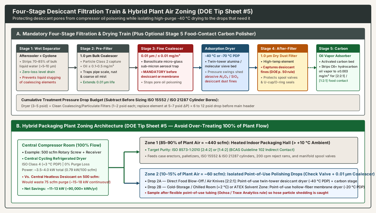
The Four-Stage Desiccant Protection Train (U.S. DOE Sourcebook, Pages 13 & 50)
The U.S. DOE Sourcebook (pages 13 and 50) states two mandatory filtration rules: “A coalescing-type filter is recommended before a desiccant-type dryer to prevent fouling of the desiccant bed. A one micron after-filter is necessary to prevent desiccant fines from entering the distribution piping.” In industrial practice, this forms a four-stage train (with an optional fifth stage for direct food contact):
- Stage 1 — Aftercooler & Centrifugal Wet Bulk Separator (with Zero-Loss Drain): Strips
70% to 85%of condensed liquid water droplets (> 5–10 µm) immediately after the compressor so downstream coalescing elements are not flooded with bulk liquid slugs. - Stage 2 —
1.0 µmGeneral-Purpose Particulate / Bulk Pre-Filter (ISO Particle Class 2): Captures pipe rust, mill scale, and coarse liquid/oil mist (≤ 0.1 to 0.5 mg/m³), protecting the fine borosilicate element downstream from premature plugging. - Stage 3 —
0.01 µmHigh-Efficiency Oil Coalescing Filter (≤ 0.01 mg/m³residual oil aerosol, Immediately Upstream of Dryer): Traps sub-micron lubricant aerosols from oil-flooded rotary screw compressors using pleated borosilicate micro-glass depth media. Without a0.01 µmcoalescer, sub-micron oil mist coats the internal pores of activated alumina and molecular sieve beads (oil poisoning), permanently blinding the desiccant within months and forcing a full-vessel re-bed. - Stage 4 —
1.0 µmHigh-Temperature Dry Particulate After-Filter (Immediately Downstream of Desiccant Dryer): Every time a desiccant tower depressurizes from100 psigto0 psigand repressurizes, bead-on-bead attrition fractures alumina and silica into fine, highly abrasive ceramic powder (desiccant fines or desiccant flour). If the1.0 µmafter-filter is omitted or torn, this abrasive dust migrates into the header:- In high-cycle directional valves—such as a pneumatic reject station firing at 200 containers per minute on our reject actuator checklist—desiccant fines wedge inside micron-clearance lapped-spool galleries, causing sluggish shifting or firing the ram on the wrong container.
- Inside
ISO 15552andISO 21287cylinders, desiccant dust mixes with boundary grease to form an abrasive lapping paste that scores aluminum barrels and wears out theU-cup(> 20 in./s) andO-ringpiston seals analyzed on our cylinder selection questions note.
- Optional Stage 5 — Activated Carbon Tower + Point-of-Use Sterile Filter (for
[2:2:1]/[1:2:1]Direct Food Contact): Because a0.01 µmcoalescing filter only captures liquid and aerosol droplets, meetingISO 8573-1 Oil Class 1(≤ 0.01 mg/m³includingC6+hydrocarbon vapor) behind an oil-flooded compressor requires an activated carbon adsorber downstream of the dryer, followed by a point-of-use sterile filter sampled after the flexible hose (air preparation questions for a packaging line).
Subtracting Dryer and Filter Pressure Drop (ΔP) and Comparing System Energy
As Josh Cosford details in Pneumatic Tips: A designer’s guide to pneumatic cylinders, compressor discharge pressure is never available in full at the cylinder work port. Before recording port pressure on the cylinder selection questions worksheet or running bore force and ISO 8778 free-air consumption formulas on the double-acting pneumatic cylinder sizing guide, account for the treatment train’s pressure drop budget:
- Refrigerated Dryer Train:
3 to 5 psidacross the dryer heat exchangers +1 to 3 psidacross a clean pre-filter =4 to 8 psid(0.28 to 0.55 bar) baseline loss. - Desiccant Dryer + 4-Stage Filter Train:
3 to 5 psidacross the desiccant bed and switching valves +3 to 7 psidacross two upstream coalescers and one downstream particulate after-filter (when elements approach their5 to 7 psidchangeout differential) =6 to 12 psid(0.41 to 0.83 bar) loss before distribution piping and valve drops are even subtracted.
Likewise, when evaluating air cylinders against electric drives on our pneumatic vs. servo motion comparison, include the dryer’s specific package power (~0.79 kW/100 scfm for refrigerated vs. ~3.0 to 3.8 kW/100 scfm for heatless PSA desiccant) on top of the compressor’s ~18 to 22 kW/100 scfm generation input. And when auditing older dryers, filter bowls, or cylinders already installed on the line, record the exact standard edition printed on the nameplate (ISO 8573-1:2010, ISO 7183, CAGI ADF 100, or CAGI ADF 200) using the method on how to read an old pneumatics part number.
Hybrid Packaging Plant Zoning (U.S. DOE Tip Sheet #5)
U.S. Department of Energy Compressed Air Tip Sheet #5: Determining the Right Air Quality for Your Compressed Air System (DOE/GO-102004-1928) emphasizes that over-treating an entire plant’s compressed air supply to match the single most stringent drop wastes both capital and continuous electrical energy:
- Single Central Desiccant Penalty (What to Avoid): If a packaging facility generates
500 scfmat100 psigand only50 scfm(10%) touches open containers or enters a chilled room while450 scfm(90%) drives indoor case-erector and palletizer cylinders, drying all500 scfmthrough a central heatless desiccant dryer wastes15% × 500 scfm = 75 scfmof purge air continuously—consuming~15 to 18 kWof compressor and dryer power year-round. - Hybrid Zoning Architecture (Recommended): Install a central cycling refrigerated compressed air dryer (
ISO Class 4,+3 °CPDP,0%purge loss,~3.5 to 4.0 kWtotal for500 scfm) to protect the entire indoor distribution header and the450 scfmof[2:4:2]pneumatic cylinders. Then isolate the50 scfmfood-contact or cold-room branch behind a backflow check valve, a0.01 µmcoalescing filter, and a dedicated50 scfmpoint-of-use desiccant or membrane polisher (-40 °Cor-20 °CPDP). Limiting-40 °Cregeneration purge to the50 scfmbranch cuts purge waste from75 scfmdown to7.5 scfm, saving more than11 kW(~90,000+ kWh/year) on an8,000-houroperating schedule while delivering verifiedISO 8573-1:2010 [2:2:1]purity at the point of use.