
Executing a quantitative compressed air leak detection program requires pairing 38 kHz to 42 kHz ultrasonic instrumentation with choked-orifice fluid mechanics and component-level troubleshooting at the machine drop. According to U.S. Department of Energy Compressed Air Tip Sheet #3: Minimize Compressed Air Leaks (DOE/GO-102004-1926) and the U.S. DOE Sourcebook (page 39), an unmaintained industrial facility routinely loses 20% to 30% of its total compressed air capacity to leaks—with Robin Marcinkus (UE Systems) noting in Compressed Air Best Practices that DOE plant assessments frequently find roughly 30% of compressor output lost to leaks and only 50% used productively. Beyond wasted electrical kilowatt-hours at the compressor room, downstream pressure droop across leaking point-of-use FRL unit (Filter-Regulator-Lubricator) assemblies and quick-disconnect couplers starves packaging cylinders of work-port pressure, slowing high-speed actuators until reject rams and case erectors miss their cycle windows.
While our parent leakage survey plan provides the printable 7-column tag-and-repair field sheet (leakage-survey-worksheet.txt) inside the compressed air section and quotes two sample cells from the 2004 DOE rate table (5.72 cfm at 1/16 in. / 90 psig and 100.9 cfm at 1/4 in. / 100 psig), this engineering guide supplies the underlying acoustic physics, instrumentation specifications, complete multi-pressure choked-orifice lookup tables (C_d = 0.97 vs. C_d = 0.61), non-production plant baseline formulas, and point-of-use frl unit diagnostic procedures required to size, execute, and verify an ultrasonic air leak survey.
| Diagnostic Method / Survey Stage | Operating Frequency & Physical Principle | Effective Stand-Off Distance | Survey Speed (100-Drop Packaging Plant) |
Flow (SCFM / NL/min) & ROI Output |
Primary Role in an ISO 50001 Leak Program |
|---|---|---|---|---|---|
ASTM E1002 Heterodyne Ultrasonic Probe (Airborne + Contact) |
Single 40 kHz (±2 kHz) piezo sensor mixed with 36 kHz local oscillator -> 2–6 kHz headphone audio + dBµV meter |
0.05 to 3 m (focusing cone); up to 10–15 m (parabolic dish) |
Baseline (1×: 2 to 4 min per drop leg via gross-to-fine sweep) |
Empirical lookup from dBµV reading or orifice estimate on DOE Tip Sheet #3 table |
Pinpointing tight valve cabinets, plus structure-borne contact probing of 5/2 valves and FRL float traps |
Phased-Array 64–124 MEMS Acoustic Imaging Camera |
Spiral array of 64–124+ digital MEMS microphones (30–50 kHz bandpass) + real-time FPGA delay-and-sum beamforming |
0.5 m to 15–30+ m (up to 50 m on large overhead header leaks) |
5× to 10× faster (15 to 30 s per zone; images multiple leaks at once) |
Automated on-screen calculation (SCFM, NL/min, and USD/yr from dB SPL + laser range + line bar/psig) |
Rapid plant-wide ultrasonic air leak survey routes, overhead ring-main scanning without lifts, and photo audit logs |
| Non-Production Compressor Load/Unload or Pump-Down Audit | Macroeconomic mass-balance timing of compressor load duty cycle (T_load / T_cycle) or receiver pressure decay (ΔP / Δt) |
Entire distribution network simultaneously (compressor room) |
30 to 60 minutes during weekend or shift-change shutdown |
Exact plant-wide aggregate leakage (total SCFM and % of compressor capacity) |
Establishing the pre-survey baseline (20%–30%) and verifying post-repair reduction to the 5%–10% DOE target |
Liquid Surfactant Bubble Solution (ASTM E515) |
Surface-tension film formation (soapy water applied by brush or spray bottle directly on pressurized joint) |
0 m (requires direct hand reach to every fitting) |
0.1× (10× slower; cannot reach overhead headers) |
Qualitative only (visual bubble cluster growth; zero flow metric) | Final zero-cost millimeter verification on crowded push-to-connect manifolds after ultrasonic pinpointing |
1. Physics of Ultrasonic Compressed Air Leak Detection (38–42 kHz Turbulent Jet Acoustics)
A human inspector walking a running packaging hall cannot locate small or medium compressed air leaks by ear. Understanding why an ultrasonic detector isolates a 0.25 mm pinhole from 3 meters away across a 90 dBA bottling floor requires examining the fluid mechanics of a choked sonic gas jet and the frequency distribution of factory noise.
Laminar Header Flow vs. Choked Turbulent Orifice Expansion (Re > 10,000)
Inside a properly sized compressed air ring main or machine drop leg, compressed air travels at low bulk velocities (5 to 10 m/s) in a stable, low-noise boundary regime. As Robin Marcinkus explains in Compressed Air Best Practices: Ultrasound Saves Energy by Detecting Compressed Air System Leaks, a leak occurs when high-pressure air escapes through a restricted orifice, cracked polymer tube, scored elastomer seal, or unsealed pipe thread into atmospheric low-pressure air (P_atm = 1.013 bar(a) = 14.7 psia).
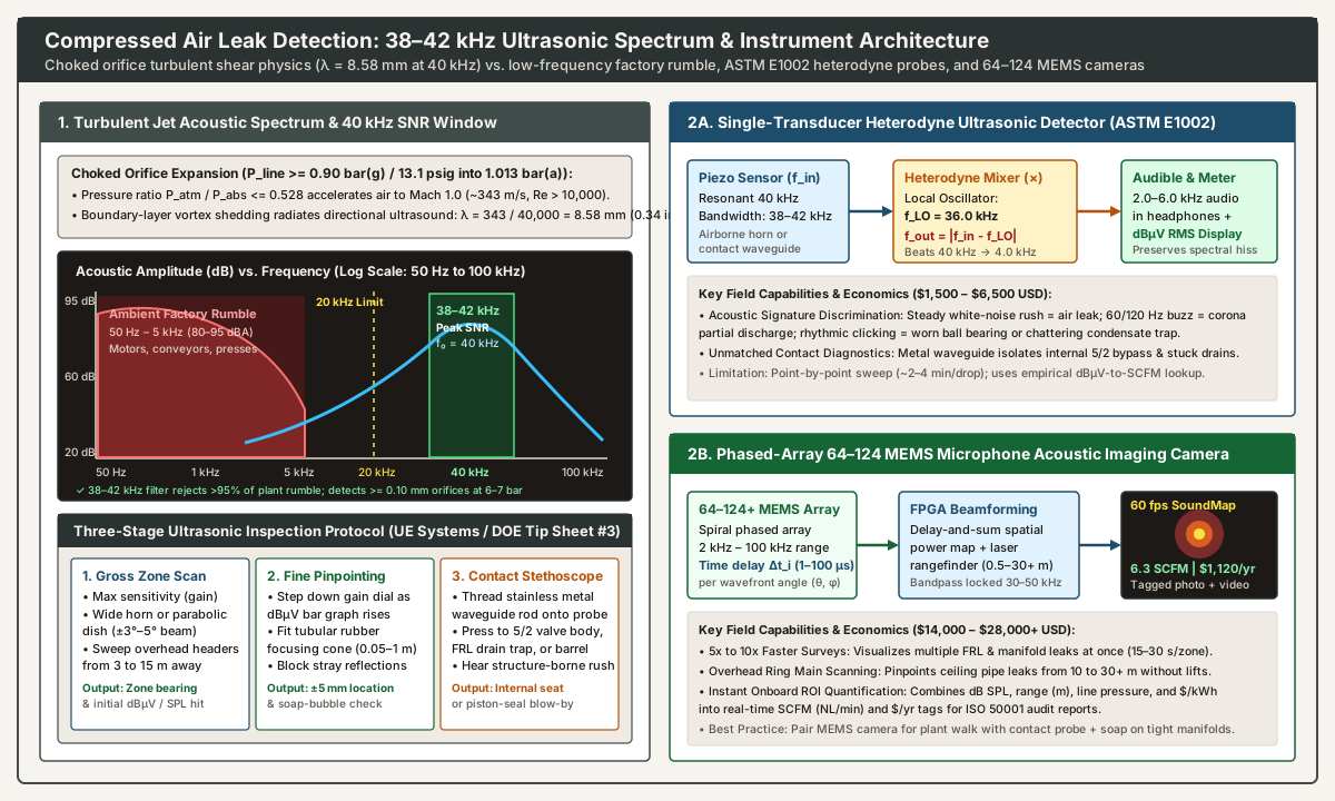
For diatomic air (adiabatic index γ = 1.40), whenever the absolute downstream-to-upstream pressure ratio across an opening falls at or below the critical sonic ratio (b_crit = 0.5283), the escaping gas accelerates to local Mach 1.0 (c ≈ 343 m/s at 20 °C) at the orifice throat (vena contracta). Because 1.013 bar(a) / 0.5283 = 1.918 bar(a), any gauge line pressure above 0.90 bar(g) (13.1 psig) produces a choked sonic jet. At standard industrial packaging line pressures of 5.5 to 7.0 bar(g) (80 to 100 psig), the exiting jet shoots into still room air at 343 m/s with a local Reynolds number exceeding Re = 10,000 to 50,000. Intensive viscous shear along the jet boundary layer sheds high-frequency turbulent eddies (micro-vortices) that radiate broadband acoustic pressure waves spanning from audible hiss (1 to 15 kHz) up to 100 kHz.
Why the 38–42 kHz Window Maximizes Signal-to-Noise Ratio (SNR)
Although human hearing cuts off near 16 to 20 kHz (and healthy young ears average ~16.5 kHz), industrial plant ambient noise is overwhelmingly concentrated at the opposite end of the spectrum:
- Low-Frequency Factory Machinery Rumble (
50 Hz to 5 kHz,80 to 95 dBA): AC induction motors (50/60 Hzand100/120 Hzmagnetic harmonics), gearbox mesh frequencies (300 Hz to 2 kHz), vibratory bowl feeders, carton erectors, and mechanical punch presses flood the audible band. In this range, a1.5 SCFMair leak is buried20 to 40 dBbelow background noise. - Ultrasonic Turbulent Shear Peak (
38 kHz to 42 kHz, centered at40 kHz): Mechanical plant rumble rolls off steeply above10 to 15 kHz, whereas the turbulent boundary-layer shear of an escaping compressed air jet maintains strong acoustic energy between25 kHzand60 kHz, peaking in signal-to-noise ratio (SNR) around38 kHz to 42 kHz. By placing a sharp electronic bandpass filter around40 kHz(or30 to 50 kHzon an acoustic camera), the instrument rejects more than 95% of audible factory noise, allowing an inspector to detect leaks while the packaging line runs at full production speed.
Short Wavelength (λ = 8.58 mm) Directionality and Detection Limits
Acoustic wavelength λ in air (speed of sound c ≈ 343 m/s at 20 °C) is inversely proportional to frequency f:
- Wavelength Equation:
λ = c / f - At
f = 100 Hz(Audible Motor Hum):λ = 343 / 100 = 3.43 m(11.25 ft). Long waves diffract effortlessly around machine frames and fill the entire room uniformly, making directional localization impossible. - At
f = 40,000 Hz(40 kHzUltrasound):λ = 343 / 40,000 = 0.00858 m = 8.58 mm(0.34 in.).
Because an 8.58 mm wave is smaller than a push-to-connect fitting nut, 40 kHz ultrasound behaves almost like a beam of light: it radiates in a highly directional cone directly from the orifice, attenuates rapidly with distance according to the inverse-square law plus atmospheric molecular absorption, and bounces cleanly off hard metal enclosures without wrapping around barriers. At 6.0 to 7.0 bar(g) (87 to 100 psig) header pressure, a 40 kHz sensor reliably detects leaks down to 0.10 to 0.25 mm (0.004 to 0.010 in.) in equivalent diameter (0.05 to 0.15 SCFM / 1.5 to 4.2 NL/min) from 1 to 3 meters away. Only when gauge pressure drops below 1.0 to 1.5 bar(g) (15 to 22 psig)—such as inside a low-pressure air-pillow fill tube—does jet exit velocity fall below sonic speed enough to require close-in scanning (< 0.3 m) or brush-on surfactant confirmation.
2. Heterodyne Ultrasonic Probes (ASTM E1002) vs. Phased-Array MEMS Acoustic Imaging Cameras
Maintenance teams conducting an ultrasonic air leak survey choose between two primary classes of ultrasonic hardware—or combine both in a two-tier workflow.
Single-Transducer Heterodyne Ultrasonic Detectors (ASTM E1002)
Governed by ASTM E1002 (Standard Practice for Leaks Using Ultrasonics), traditional handheld ultrasonic leak detectors mount a single piezoelectric crystal resonant at 40 kHz (±2 kHz bandwidth) inside a directional housing. Because a 40 kHz electrical signal cannot be heard by the operator, the instrument passes the amplified transducer signal (f_in = 38 to 42 kHz) into a nonlinear analog or digital mixer (heterodyne circuit) alongside a stable internal local oscillator (f_LO, typically 36.0 kHz):
- Heterodyne Beat-Frequency Equation:
f_audio = |f_in - f_LO| - Audible Translation: A
40.0 kHzleak signal mixed with a36.0 kHzlocal oscillator produces a4.0 kHzdifference tone (2.0 to 6.0 kHzacross the38–42 kHzpassband) delivered directly into industrial noise-attenuating headphones, while displaying root-mean-square (RMS) signal strength indBµV(decibels relative to1 microvolt) on an LED or LCD bar graph. - Spectral Signature Discrimination: Unlike simple threshold beepers, heterodyning preserves the exact amplitude-modulation envelope of the ultrasonic source. A trained technician immediately distinguishes the steady, unmodulated white-noise hiss of a compressed air leak from the
60 Hz / 120 Hz(or50 Hz / 100 Hz) buzzing fry of high-voltage electrical partial discharge (coronaortrackinginside a motor starter cabinet) and the rhythmic metallic clicking of a dry ball bearing.
Three-Stage Gross-to-Fine and Contact Scanning Protocol
Following the inspection methodology outlined in U.S. DOE Tip Sheet #3 and Robin Marcinkus’s field guide in Compressed Air Best Practices, a single-transducer survey executes three steps:
- Stage 1 — Gross Zone Scan (
Wide Horn or Parabolic Dish): Set instrument sensitivity (gain) to maximum (e.g., 80–100 dB). Sweep the wide-angle airborne horn across packaging machine frames from2 to 5 metersaway. For overhead distribution headers5 to 15 metersabove the floor, snap on an acoustic parabolic dish concentrator, which narrows the acceptance angle to±3° to 5°and focuses distant40 kHzwavefronts onto the piezo element. - Stage 2 — Fine Pinpointing (
Gain Attenuation + Tubular Rubber Focusing Cone): Walk toward the loudestdBµVbearing. As the bar graph pegs near100%, step the sensitivity dial down in5 to 10 dBincrements and slip the flexible tubular rubber focusing probe over the nosecone. The elastomer tube shields the sensor from off-axis reflections off stainless-steel guard doors, narrowing the field of view until the leak is isolated within±5 mm. If four push-to-connect fittings sit12 mmapart on a valve island, dab a drop of surfactant bubble solution on the suspect collet to confirm which port is bubbling. - Stage 3 — Structure-Borne Contact Probe Mode (
Metal Waveguide Stethoscope): Unscrew the airborne horn and thread a solid stainless-steel contact waveguide rod onto the transducer. Pressing the metal tip firmly against an anodized aluminum5/2directional valve body, a cast-iron moisture separator trap, or an frl unit filter bowl boss couples structure-borne40 kHzvibration directly into the crystal—exposing internal valve-seat or condensate-drain bypass that never vents directly into room air at the housing.
Phased-Array 64–124 MEMS Microphone Acoustic Imaging Cameras
Over the past decade, industrial compressed air leak detection in multi-line packaging plants has been transformed by phased-array acoustic imaging cameras (such as the Fluke ii900 / ii910, Teledyne FLIR Si124 / Si2-LD, and Distran Ultra Pro). Instead of a single directional crystal, an acoustic camera arranges 64 to 124+ digital Micro-Electro-Mechanical Systems (MEMS) omnidirectional microphones in a non-redundant spiral array surrounding a wide-angle optical camera:
- Real-Time Delay-and-Sum Beamforming: When a
40 kHzspherical wavefront from a leak at angular coordinates(θ, φ)strikes the camera faceplate, it reaches each microphone at a slightly different microsecond time of arrival (Δt_i ≈ 1 to 100 µs). An onboard Field-Programmable Gate Array (FPGA) continuously shifts and sums all64 to 124channels across thousands of grid directions (60 frames per second), rendering a color-coded Sound Pressure Level (dB SPL) heatmap directly over the live optical image. 5× to 10×Faster Survey Walks: Rather than sweeping every fitting one by one with headphones, the inspector views an entire3-metervalve cabinet or12-meter-highceiling pipe rack on screen at once. Multiple simultaneous leaks appear as distinct hot spots, reducing inspection time on a100-droppackaging facility from4–6 hoursdown to30 to 45 minutes(75% to 90%labor reduction).- Automated Onboard
SCFM(NL/min) and Annual Cost (USD/yr) Quantification: By pairing the measured multi-frequency ultrasonicdB SPLintensity with an integrated laser or stereo-vision distance sensor (0.5 m to 30+ mrange) and user-entered header pressure (barorpsig), compressor specific power (kW/100 SCFM), operating hours (hr/yr), and electricity tariff (USD/kWh), the camera’s onboard acoustic-to-flow regression model computes and stamps the estimated leak flow rate (SCFMorNL/min) and annualized dollar waste (USD/yr) directly onto each saved JPEG photo—feeding directly into theTagandFlowcolumns of our leakage survey plan.
3. Choked Sonic Orifice Flow Mathematics, U.S. DOE Tip Sheet #3 Lookup Tables, and Annual Energy ROI
When logging an ultrasonic air leak survey without an auto-quantifying camera—or when verifying camera estimates against physical defect dimensions for capital repair justification—engineers compute leak flow rate from choked adiabatic orifice discharge equations and the published U.S. DOE Compressed Air Tip Sheet #3 lookup table.
Governing Choked Sonic Orifice Equations (Imperial SCFM & ISO 8778 Metric NL/min)
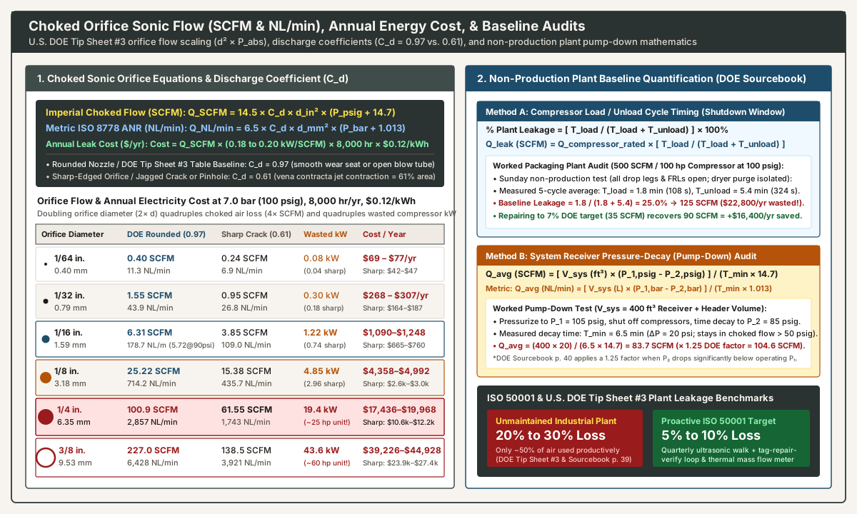
As established in Section 1, any compressed air leak from a header above 13.1 psig (0.90 bar(g)) into 14.7 psia (1.013 bar(a)) ambient air is choked (Mach = 1.0) at the throat. In choked sonic flow, downstream atmospheric pressure fluctuations have zero effect on mass flow rate; volumetric free-air leakage scales strictly linearly with absolute upstream supply pressure (P_abs) and with the square of equivalent orifice diameter (d²):
- Imperial Choked Orifice Equation (
Fliegner / Moss Formulaat60–68 °FStandard Air):Q_SCFM = 14.5 × C_d × d_in² × P_psia = 14.5 × C_d × d_in² × (P_psig + 14.7)whereQ_SCFMis free-air leak rate in Standard Cubic Feet per Minute (14.7 psia,60–68 °F),C_dis the dimensionless orifice discharge coefficient (0.61 to 0.97),d_inis equivalent circular orifice diameter in inches (in.), andP_psia = P_psig + 14.7is absolute line pressure in pounds per square inch absolute. - Metric
ISO 8778ANR Choked Orifice Equation (NL/minat1.013 bar(a),20 °C):Q_NL_min = 6.5 × C_d × d_mm² × P_bar,abs = 6.5 × C_d × d_mm² × (P_bar + 1.013)where1 SCFM = 28.317 NL/min(Normal Liters per minute, matching theISO 8778free-air reference standard used on our double-acting pneumatic cylinder sizing guide and pneumatic flow control valve sizing guide).
Reconciling Discharge Coefficients: Well-Rounded (C_d = 0.97) vs. Sharp-Edged (C_d = 0.61)
Engineers comparing different pneumatic handbooks frequently notice a ~37% difference in listed SCFM for the same hole diameter and pressure. U.S. DOE Tip Sheet #3 (page 1) explicitly states the governing fluid-dynamic rule beneath its table: “For well-rounded orifices, multiply values by 0.97 and for sharp ones, multiply by 0.61.”
- Well-Rounded Nozzle / Published DOE Tip Sheet #3 Baseline (
C_d = 0.97to1.00): When air escapes through a smoothly contoured nozzle, an open copper blow-off tube, or a smoothly eroded valve seat, fluid streamlines remain nearly parallel to the hole walls (minimal vena contracta contraction). AtP = 100 psig(114.7 psia) andd = 1/16 in.(0.0625 in.), the unfactored formula gives14.5 × 1.00 × (0.0625)² × 114.7 = 6.498 SCFM, and multiplying byC_d = 0.97gives6.30 to 6.31 SCFM—matching the exact6.31 cfmcell printed in U.S. DOE Tip Sheet #3. - Sharp-Edged Orifice / Jagged Crack or Pinhole (
C_d = 0.61): When air escapes through a radial split in polyurethane (PU) tubing, a pinhole in PTFE thread tape, or a cracked polycarbonate frl unit bowl lip, radial momentum forces the converging streamlines to contract inward downstream of the physical aperture. The sonic throat area (vena contracta) contracts to approximately61%of the geometric hole area (C_d = 0.61). Multiplying the DOE Tip Sheet #3 baseline by0.61yields3.85 SCFM(6.31 × 0.61) for a1/16 in.sharp-edged crack at100 psig.
Table 3A: Complete U.S. DOE Tip Sheet #3 Multi-Pressure Orifice Leakage Matrix (CFM)
For direct reference alongside our parent leakage survey plan, the table below reproduces the complete multi-pressure baseline matrix from U.S. DOE Compressed Air Tip Sheet #3 (page 1, used with permission from Compressed Air Challenge training):
Supply Pressure (psig / bar(g)) |
1/64 in. (0.40 mm) |
1/32 in. (0.79 mm) |
1/16 in. (1.59 mm) |
1/8 in. (3.18 mm) |
1/4 in. (6.35 mm) |
3/8 in. (9.53 mm) |
|---|---|---|---|---|---|---|
70 psig (4.8 bar) |
0.29 cfm |
1.16 cfm |
4.66 cfm |
18.62 cfm |
74.4 cfm |
167.8 cfm |
80 psig (5.5 bar) |
0.32 cfm |
1.26 cfm |
5.24 cfm |
20.76 cfm |
83.1 cfm |
187.2 cfm |
90 psig (6.2 bar) |
0.36 cfm |
1.46 cfm |
5.72 cfm |
23.10 cfm |
92.0 cfm |
206.6 cfm |
100 psig (6.9 bar) |
0.40 cfm |
1.55 cfm |
6.31 cfm |
25.22 cfm |
100.9 cfm |
227.0 cfm |
125 psig (8.6 bar) |
0.48 cfm |
1.94 cfm |
7.66 cfm |
30.65 cfm |
122.2 cfm |
275.5 cfm |
Engineering application note (U.S. DOE Tip Sheet #3): The baseline table values above incorporate a nominal smooth orifice profile (C_d ≈ 0.97). For sharp-edged cracks, splits, or thread pinholes, multiply the cell value by 0.61.
Table 3B: Packaging Line Orifice Flow (6 bar & 7 bar), Wasted Power (kW), and Annual Energy Cost (USD/yr)
To convert orifice flow into compressor shaft power (kW) and annual electricity cost (USD/yr) on a three-shift packaging plant schedule, apply the standard industrial rotary screw compressor specific power benchmark of 18 to 20 kW per 100 SCFM (0.18 to 0.20 kW/SCFM, or 6.36 to 7.06 kW per m³/min), 8,000 operating hours/year, and a representative industrial electricity tariff of USD 0.12 / kWh:
- Annual Cost Equation:
Cost_annual (USD/yr) = Q_SCFM × Specific_Power (kW/SCFM) × 8,000 hr/yr × Electricity_Rate (USD/kWh) - Unit Cost per SCFM-Year (
8,000 hr/yratUSD 0.12/kWh):- At
0.18 kW/SCFM(18 kW / 100 SCFM):1.0 SCFMwastes1,440 kWh/yr=USD 172.80 / yr per SCFM. - At
0.20 kW/SCFM(20 kW / 100 SCFM, including dryer and filter pressure drop):1.0 SCFMwastes1,600 kWh/yr=USD 192.00 / yr per SCFM.
- At
Orifice Diameter (in. / mm) |
Flow at 6.0 bar (87 psig) Rounded 0.97 / Sharp 0.61 |
Flow at 7.0 bar (100 psig) Rounded 0.97 / Sharp 0.61 |
Wasted Compressor Power at 7.0 bar (18–20 kW / 100 SCFM) |
Annual Electricity Cost at 7.0 bar (8,000 hr, USD 0.12/kWh) |
Typical Packaging Line & FRL Unit Defect Source |
|---|---|---|---|---|---|
1/64 in. (0.40 mm) |
0.35 SCFM (9.9 NL/min) / 0.21 SCFM (6.0 NL/min) |
0.40 SCFM (11.3 NL/min) / 0.24 SCFM (6.9 NL/min) |
0.072–0.080 kW (rounded) / 0.044–0.048 kW (sharp) |
USD 69 to 77 / yr (rounded) / USD 42 to 47 / yr (sharp) | Micro-pinhole in pipe thread sealant, dry banjo swivel O-ring, or dusty gauge port |
1/32 in. (0.79 mm) |
1.40 SCFM (39.6 NL/min) / 0.85 SCFM (24.2 NL/min) |
1.55 SCFM (43.9 NL/min) / 0.95 SCFM (26.8 NL/min) |
0.28–0.31 kW (rounded) / 0.17–0.19 kW (sharp) |
USD 268 to 298 / yr (rounded) / USD 164 to 182 / yr (sharp) | Side-loaded Ø6 or Ø8 mm push-to-connect (PTC) tube collet or weeping cylinder rod wiper |
1/16 in. (1.59 mm) |
5.58 SCFM (158.0 NL/min) / 3.40 SCFM (96.4 NL/min) |
6.31 SCFM (178.7 NL/min) / 3.85 SCFM (109.0 NL/min) |
1.14–1.26 kW (rounded) / 0.69–0.77 kW (sharp) |
USD 1,090 to 1,212 / yr (rounded) / USD 665 to 739 / yr (sharp) | Grooved quick-disconnect (QD) coupler plug, crazed polycarbonate FRL bowl lip, or torn regulator diaphragm |
1/8 in. (3.18 mm) |
22.40 SCFM (634.3 NL/min) / 13.66 SCFM (386.9 NL/min) |
25.22 SCFM (714.2 NL/min) / 15.38 SCFM (435.7 NL/min) |
4.54–5.04 kW (rounded) / 2.77–3.08 kW (sharp) |
USD 4,358 to 4,842 / yr (rounded) / USD 2,658 to 2,953 / yr (sharp) | FRL filter float auto-drain jammed on scale, split Ø8 mm PU tube, or blown piston seal bypassing out 5/2 exhaust |
1/4 in. (6.35 mm) |
89.30 SCFM (2,529 NL/min) / 54.47 SCFM (1,543 NL/min) |
100.9 SCFM (2,857 NL/min) / 61.55 SCFM (1,743 NL/min) |
18.16–20.18 kW (~25 hp!) (rounded) / 11.08–12.31 kW (sharp) |
USD 17,436 to 19,373 / yr (rounded) / USD 10,636 to 11,818 / yr (sharp) | Whipped-off QD whip hose, shattered polycarbonate bowl, open 1/4 in. copper blow tube, or stuck ball drain |
3/8 in. (9.53 mm) |
200.8 SCFM (5,686 NL/min) / 122.5 SCFM (3,468 NL/min) |
227.0 SCFM (6,428 NL/min) / 138.5 SCFM (3,921 NL/min) |
40.86–45.40 kW (~60 hp!) (rounded) / 24.93–27.70 kW (sharp) |
USD 39,226 to 43,584 / yr (rounded) / USD 23,928 to 26,592 / yr (sharp) | Ruptured flexible drop-leg whip hose, failed central receiver drain trap, or open bypass valve |
Notice the quadratic d² scaling law: a single 1/4 in. (6.35 mm) open blow-off tube or failed receiver drain trap at 100 psig wastes 100.9 SCFM—consuming the entire output of a dedicated 25 hp (19 kW) rotary screw compressor and costing up to USD 19,373 per year by itself.
4. Plant-Wide Non-Production Baseline Quantification & Worked Ultrasonic Survey ROI
Before starting a tag-and-repair walk with an ultrasonic probe or acoustic camera, an ISO 50001 energy audit measures the facility’s aggregate baseline leak rate during a non-production window (weekend shutdown or shift change) with all packaging machinery stopped, all drop-leg isolation valves and frl unit regulators left open at normal operating pressure, and intentional desiccant/membrane dryer purges isolated or subtracted (U.S. DOE Sourcebook, page 40).
Method 1: Compressor Start/Stop or Load/Unload Cycle Timing (U.S. DOE Sourcebook, Page 40)
In facilities served by start/stop or load/unload controlled compressors, leaks cause the compressor to cycle repeatedly between its cut-in and cut-out pressure setpoints even when zero production machines are cycling. Measure the on-load duration (T_load) and unloaded duration (T_unload) across 4 to 6 consecutive cycles:
- Percentage Plant Leakage Equation:
% Plant Leakage = [ T_load / (T_load + T_unload) ] × 100% - Aggregate Leak Flow Rate (
SCFM):Q_leak (SCFM) = Q_compressor_capacity (SCFM) × [ T_load / (T_load + T_unload) ] - Conditional Worked Audit Example: Suppose a beverage packaging plant operates a
500 SCFM(100 hp/75 kWnominal) rotary screw compressor in load/unload mode at100 psigduring a Sunday line shutdown. Across five cycles, the compressor loads for an average ofT_load = 1.80 minutes(108 s) and unloads forT_unload = 5.40 minutes(324 s, total cycle7.20 minutes).- Baseline Leak Percentage:
% Leakage = 1.80 / (1.80 + 5.40) = 25.0%(right in the middle of the20%–30%unmaintained industrial range cited in U.S. DOE Tip Sheet #3). - Baseline Wasted Flow & Cost:
Q_leak = 500 SCFM × 0.250 = 125.0 SCFM(3,540 NL/min). At0.19 kW/SCFM,8,000 hr/yr, andUSD 0.12/kWh, leaks alone draw23.75 kWand waste USD 22,800 per year.
- Baseline Leak Percentage:
Method 2: Receiver and Header Pressure-Decay (Pump-Down) Test (U.S. DOE Sourcebook, Page 40)
When a plant runs Variable-Speed Drive (VSD), inlet-valve modulation, or variable-displacement compressors that do not cycle cleanly between full load and unload, perform a system pressure-decay (pump-down) audit:
- Calculate Total Pressurized System Volume (
V_sysinft³orL): Sum the internal volumes of the wet air receiver, dry air receiver, oil separator vessel, and main overhead ring-main piping (e.g., 1 US gallon = 0.13368 ft³ = 3.785 L). - Pressurize and Isolate Supply: Bring the distribution system to normal operating cut-out pressure
P_1(e.g., 105 psig/7.24 bar(g)), then shut off the compressor (or close the main discharge block valve upstream of the measured receiver volume). - Time Pressure Decay (
T_min): Using a calibrated digital pressure transducer and stopwatch, record the elapsed timeT_min(in minutes) required for header pressure to decay toP_2(choosing P_2 >= 50 psig / 3.5 bar(g) so all leaks remain in choked sonic flow):- Imperial Pump-Down Formula (
SCFM):Q_avg (SCFM) = [ V_sys (ft³) × (P_1,psig - P_2,psig) ] / (T_min × 14.7) - Metric Pump-Down Formula (
NL/min):Q_avg (NL/min) = [ V_sys (L) × (P_1,bar - P_2,bar) ] / (T_min × 1.013) - DOE Sourcebook
1.25×Decay Multiplier: Because choked leak mass flow decreases linearly as header pressure drops fromP_1down toP_2, page 40 of the U.S. DOE Sourcebook applies a1.25correction multiplier (Q_leak,P1 = 1.25 × Q_avg) whenP_2drops significantly (such as50%of initial gauge pressure), or you can time a narrow10 to 15 psidrop centered near normal operating pressure.
- Imperial Pump-Down Formula (
- Conditional Worked Pump-Down Example: A multi-line packaging facility has a combined wet/dry receiver and
4-inchloop header volume ofV_sys = 400 ft³(~2,992 gallons/11,327 L). When the compressors are stopped atP_1 = 105 psig, header pressure falls toP_2 = 85 psig(ΔP = 20 psi) inT_min = 6.50 minutes:Q_avg = (400 × 20) / (6.50 × 14.7) = 8,000 / 95.55 = 83.7 SCFM(2,370 NL/minat95 psigmean pressure, or104.6 SCFMapplying the DOE1.25×multiplier).
Method 3: Worked Ultrasonic Air Leak Survey ROI & Payback Calculation
Continuing the 500 SCFM packaging plant above (125.0 SCFM baseline leakage = 25.0% of capacity), suppose the maintenance team conducts a 1-day ultrasonic air leak survey across four bottling and case-packing lines using a phased-array MEMS camera paired with a heterodyne contact probe, logging 48 numbered tags onto the leakage survey plan worksheet:
| Leak Severity Tier & Orifice Class | Tagged Count (48 Total) |
Defect Examples Logged on Packaging Lines | Flow per Leak at 100 psig (SCFM) |
Total Tier Leakage (SCFM / NL/min) |
Annual Electricity Cost (8,000 hr, USD 0.12/kWh, 0.19 kW/SCFM) |
|---|---|---|---|---|---|
Tier 1 — Major Leaks (~1/8 in. / 3.18 mm sharp C_d = 0.61) |
3 tags |
2 jammed FRL filter float auto-drains + 1 blown ISO 15552 cylinder piston seal venting out 5/2 Port 3 |
15.38 SCFM each |
46.14 SCFM (1,307 NL/min) |
USD 8,416 / yr (8.77 kW wasted) |
Tier 2 — Medium Leaks (~1/16 in. / 1.59 mm sharp C_d = 0.61) |
11 tags |
5 worn brass QD couplers, 3 bleeding ISO 6953 regulator bonnets, 3 crazed polycarbonate FRL bowls |
3.85 SCFM each |
42.35 SCFM (1,199 NL/min) |
USD 7,725 / yr (8.05 kW wasted) |
Tier 3 — Minor Leaks (~1/32 in. / 0.79 mm sharp C_d = 0.61) |
34 tags |
26 side-loaded Ø8 mm push-to-connect (PTC) collets, 5 banjo speed-controller O-rings, 3 pipe thread joints |
0.95 SCFM each |
32.30 SCFM (915 NL/min) |
USD 5,892 / yr (6.14 kW wasted) |
| Survey Total (Accounted Tags) | 48 tags |
Notice Pareto distribution: Top 14 leaks (29% of tags) account for 73.3% (88.5 SCFM) of total loss! |
— | 120.79 SCFM (3,421 NL/min, 96.6% of pump-down baseline) |
USD 22,033 / yr (22.95 kW wasted) |
- Closed-Loop Repair & Verification Economics:
- Repairing
42 of the 48tagged leaks during the next planned maintenance shift (replacing the2jammed float drains with zero-loss capacitive drains, rebuilding3regulators, swapping3crazed bowls to metal bowls, eliminating5unnecessaryQDcouplers, and square-cutting/re-terminating29PTCfittings) eliminates90.0 SCFMof leakage, bringing residual plant leakage down to35.0 SCFM(7.0%of500 SCFMcapacity)—well inside the5% to 10%U.S. DOE /ISO 50001target. - Gross Annual Electricity Savings:
90.0 SCFM × 0.19 kW/SCFM × 8,000 hr/yr × USD 0.12/kWh = 136,800 kWh/yr=USD 16,416 / year. - Survey & Repair Investment:
8 hoursinspection +24 hourstechnician repair labor (32 hr × USD 65/hr = USD 2,080) + replacement zero-loss drains, metal FRL bowls, fittings, and seal kits (USD 1,420) =USD 3,500total project cost. - Simple Payback Period:
USD 3,500 / (USD 16,416 / 12 months)=2.56 months(~78 days,469%first-year ROI). - Critical Post-Repair Control Step (
U.S. DOE Tip Sheet #3): As emphasized on our parent leakage survey plan, fixing leaks on the factory floor only turns into electrical savings on the utility bill when compressor controls are adjusted to match the lower demand (such as lowering cascade header pressure bands, switching a base-load unit to trim/auto-stop, or allowing a VSD compressor to turn down).
- Repairing
5. High-Probability Point-of-Use Leak Points: FRL Unit Assemblies, Drop Legs, and 5/2 Valve Exhausts
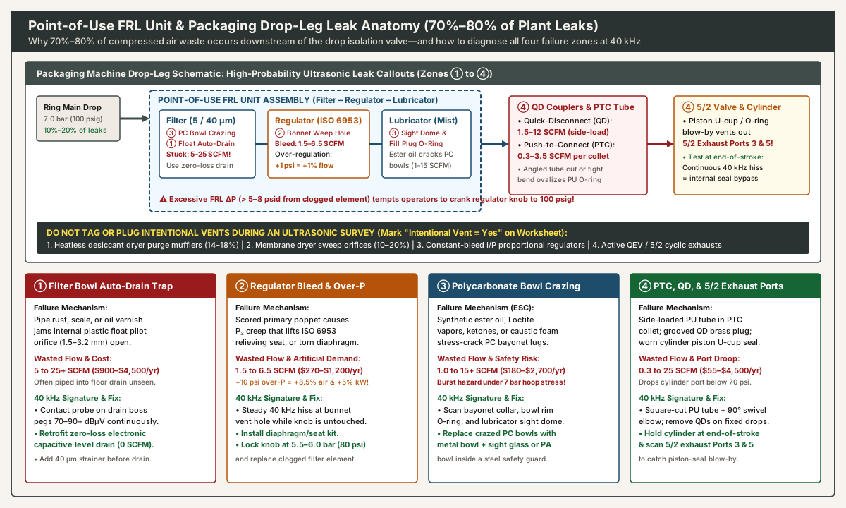
Overhead welded steel, brazed copper, or extruded aluminum ring mains rarely account for more than 10% to 20% of total facility leakage once hydrostatically or pneumatically pressure-tested at commissioning. In packaging plants, 70% to 80% of all compressed air waste occurs downstream of the drop-leg isolation ball valve—specifically inside point-of-use FRL unit (frl unit) assemblies, flexible whip hoses, push-to-connect manifolds, and reciprocating actuators subjected to continuous 5 to 50 Hz frame vibration, thermal washdowns, and operator adjustment (U.S. DOE Tip Sheet #3, page 1).
1. Filter Bowl Condensate Auto-Drains (Float Traps Jammed on Pipe Scale vs. Zero-Loss Drains)
As noted on our sibling air preparation questions for a packaging line guide, a point-of-use frl unit begins with a particulate/coalescing filter (5 µm or 40 µm sintered bronze or polyethylene element) and centrifugal louver that spins out liquid water droplets and compressor lubricant carryover into the lower quiet zone of the filter bowl.
- Mechanical Float Auto-Drain Failure Physics: Most standard FRL filter bowls ship with an internal mechanical float auto-drain (
~1.5 to 3.2 mmpilot orifice). When liquid condensate accumulates, a small hollow plastic float rises and unseats a needle seal to blow liquid out the bottom1/8 in.drain nipple. Over months of service, pipe rust, mill scale, PTFE tape shreds, or emulsified compressor oil sludge fouls the float guide stem or wedges directly beneath the fluoroelastomer seat—locking the drain orifice continuously open. Because plant plumbers routinely pipe FRL drain tubing into an opaque floor trench, condensate manifold, or machine drip pan, a single jammed float drain silently blows5 to 25+ SCFM(USD 900 to 4,500+ / yr) 24 hours a day without any visible mist in the aisle. 40 kHzUltrasonic Signature & Fix: Press the heterodyne contact waveguide probe against the brass drain fitting at the bottom of the filter bowl (or aim the airborne focusing cone at the drain discharge tube). A healthy float or electronic drain reads0 dBµVabove ambient between brief0.5 to 2 secondpurge bursts; a jammed drain pegs the meter at70 to 90+ dBµVcontinuously. Isolate the drop, disassemble and wash the float mechanism in warm mild soap solution, install a40 µmY-strainer ahead of heavy condensate traps, or replace mechanical float drains and open-timer solenoid valves with zero-loss electronic capacitive level-sensing drains (compressed air dryer selection: refrigerated vs. desiccant).
2. ISO 6953 Pressure Regulator Diaphragm Bleed, Seat Creep, and Artificial Demand (U.S. DOE Tip Sheet #4)
The middle module of an frl unit is a spring-loaded diaphragm or piston pressure regulator conforming to ISO 6953 (Pneumatic fluid power —Compressed air pressure regulators and filter-regulators). Industrial packaging regulators are almost universally self-relieving designs: when an operator dials secondary outlet pressure P_2 downward, a central relieving port in the diaphragm disc lifts off its stem seat so trapped downstream air vents safely through the bonnet weep hole (under the adjustment knob). Two expensive failure modes occur here:
- Continuous Bonnet Weep from a Scored Poppet or Ruptured Diaphragm (
1.5 to 6.5 SCFM): When a piece of pipe scale or desiccant dust (compressed air dryer selection) scores the primary inlet poppet seal, high-pressure supply air (P_1 = 100 psig) leaks slowly into the secondary chamber (pressure creep). AsP_2creeps2 to 5 psiabove the spring setpoint, the self-relieving seat lifts and vents continuously out the plastic bonnet hole. Likewise, cyclic fatigue cracks the nitrile (NBR) diaphragm, blowing air straight through the spring cage (costing USD 270 to 1,200/yrper regulator). Scan every regulator bonnet vent hole at40 kHzwhile the machine is idle: any steady ultrasonic hiss when the knob is stationary requires an OEM diaphragm-and-poppet rebuild kit. - Artificial Demand from Operator Over-Pressurization (U.S. DOE Tip Sheet #4 & Sourcebook Pages 25–28): When a point-of-use FRL filter element plugs with oil/dust (
creating a 10 to 18 psid pressure drop instead of the clean 1 to 3 psid baseline), operators frequently crank the frl unit regulator knob from the design5.5 bar(80 psig) all the way up to full header pressure (7.0 bar / 100 psig) to keep a cylinder moving at speed. Because choked sonic flowQis proportional to absolute pressureP_psia:- Downstream Flow & Leak Penalty: Every
+1 psi(+0.07 bar) increase in regulated manifold pressure increases both actuator air consumption and downstream leak flow rates by~0.85% to 1.0%(raising a regulator from 80 psig to 100 psig increases every downstream fitting leak by (114.7 / 94.7) - 1 = +21.1%!). - Compressor Shaft Power Rule of Thumb (U.S. DOE Sourcebook, p. 25): Raising compressor discharge pressure by
+2 psiincreases compressor shaft power consumption by approximately1.0%(+10 psi header elevation = +5% compressor electricity). - Permanent Fix: Replace FRL filter elements whenever differential pressure reaches
5 to 7 psid(0.35 to 0.50 bar), dial the regulator back to the minimum work-port pressure verified on our cylinder selection questions worksheet (typically 5.5 to 6.0 bar / 80 to 87 psig), and snap tamper-resistant locking caps onto all frl unit adjustment knobs.
- Downstream Flow & Leak Penalty: Every
3. Polycarbonate (PC) FRL Bowl Environmental Stress Cracking (“Crazing”) and Seal O-Rings
Transparent polycarbonate (PC) filter and lubricator bowls—along with transparent lubricator drip-rate sight domes—are amorphous thermoplastics under continuous biaxial hoop tensile stress (6 to 10 bar). Polycarbonate is acutely vulnerable to Environmental Stress Cracking (ESC / spiderweb “crazing”) when exposed to trace vapors or droplets of incompatible industrial chemicals:
- Incompatible Chemical Triggers: Synthetic compressor lubricants (
phosphate esters, diesters, polyalkylene glycols), anaerobic pipe thread-locking compounds (methacrylate / Loctite vapors or liquid drips applied to adjacent fittings), ketone and ester washdown solvents (acetone, MEK, ethyl acetate), chlorinated degreasers, and alkaline caustic foam cleaners used in food and beverage packaging halls. - Failure Progression &
40 kHzDetection: Chemical attack initiates microscopic silver spiderweb fissures at the high-stress upper bayonet locking lugs or bowl thread roots, plus around the lubricator oil-fill plug O-ring and sight dome. These hairline cracks bleed1.0 to 15+ SCFM(emitting a sharp 40 kHz ultrasonic jet along the bowl collar) before the embrittled bowl shatters violently under line pressure. - Mandatory Safety & Replacement Rule: Never wipe a polycarbonate FRL bowl with solvent rags. If an ultrasonic air leak survey or visual walk detects crazing, cloudiness, or bayonet-seam leakage, immediately isolate and depressurize the drop leg. Match the existing body series and thread code using our guide on how to read an old pneumatics part number and upgrade to a die-cast aluminum or zinc metal bowl with a flush glass/polyamide sight gauge, or specify a chemical-resistant polyamide (
PA/ nylon) bowl enclosed inside a perforated steel safety guard.
4. Push-to-Connect (PTC) Collets, Quick-Disconnect (QD) Couplers, and 5/2 Valve Exhaust Diagnostics
Downstream of the frl unit, three high-density component families account for the majority of individual leak tags on a packaging machine frame:
- Push-to-Connect (
PTC) Polymer Tube Fittings (0.3 to 3.5 SCFMper port):PTCfittings rely on a toothed stainless-steel collet ring to grip the outside diameter of polyurethane (PU, Shore95A–98A) or polyamide (PA12) tubing while an internalNBRO-ring seals against the outer tube wall. As Ruby Ochoa notes in Compressed Air Best Practices (cited on our air preparation questions for a packaging line page), flexible hoses and O-rings age and shed particles downstream. InPTCjoints, three installation errors cause immediate40 kHzleaks:- Cutting tubing at an oblique angle with diagonal wire cutters instead of a square guillotine tube cutter (
leaving the tube end unseated past the O-ring); - Routing tubing with a bend radius tighter than
R_min, which applies radial side-load to the release sleeve, ovalizes the internal O-ring, and scores a groove into the softPUwall; - Reciprocating cable-carrier flexing without a
90°swivel banjo elbow (pneumatic flow control valve sizing guide).
- Cutting tubing at an oblique angle with diagonal wire cutters instead of a square guillotine tube cutter (
- Quick-Disconnect (
QD) Plug-and-Socket Couplers (1.5 to 12 SCFM): IndustrialQDcouplers feeding manual blow guns and change-part sub-plates suffer constant side-load leverage from hanging coiled hoses and grit intrusion when brass plugs are dragged across the concrete floor. Design Rule: Never use quick-disconnect couplers for permanent machine supply connections; hard-pipe permanent drops with threaded unions or manifold blocks, and mount necessaryQDsockets vertically downward to eliminate side-load O-ring distortion. - Diagnosing Internal Cylinder Piston-Seal Blow-By via
5/2Valve Exhaust Mufflers (Ports 3 & 5): As Josh Cosford explains in Pneumatic Tips: A designer’s guide to pneumatic cylinders, side loads wear out cylinder rod seals and internalU-cuporO-ringpiston seals prematurely. While a worn rod gland seal hisses visibly where the piston rod exits the front head (detectable at 40 kHz around the rod wiper), an internal piston seal leak never escapes through the aluminum cylinder barrel. Instead, high-pressure air in the driving chamber (e.g., Cap Port 4) blows past the scored piston seal into the opposing vented chamber (Rod Port 2), travels backward through the connecting tube into the5/2directional control valve, and vents continuously out of the exhaust muffler on Port 3 (R) or Port 5 (S)!- Two-Step Ultrasonic Isolation Test: With the packaging line paused in a safe, pressurized hold state (
all cylinders stationary at end of stroke), hold the40 kHzultrasonic probe (or view with theMEMScamera) across the5/2valve island’s sintered bronze or polyethylene exhaust mufflers (Ports 3 and 5). When no cylinder is moving, exhaust mufflers must be 100% silent (0 SCFM). If Port 3 or Port 5 emits a steady40 kHzultrasonic jet while all actuators are stationary, pinch or plug the polyurethane work-port tube leading to each cylinder one by one:- If plugging Cylinder A’s vented return tube stops the exhaust muffler hiss, Cylinder A’s internal piston seal is bypassing (double-acting pneumatic cylinder sizing guide).
- If the exhaust muffler continues hissing with the cylinder ports plugged, the
5/2directional valve’s internal spool seal is worn and bypassing supplyPort 1 (P)directly to exhaust.
- Two-Step Ultrasonic Isolation Test: With the packaging line paused in a safe, pressurized hold state (
Point-of-Use Component Diagnostic & Remediation Matrix
Drop-Leg / FRL Unit Component |
Dominant Failure Mechanism | Typical Leak Rate (SCFM / NL/min at 7 bar) |
Annual Energy Cost (USD/yr at USD 0.12/kWh) |
40 kHz Ultrasonic Survey Technique |
Permanent Engineering Remediation |
|---|---|---|---|---|---|
| FRL Filter Bowl Mechanical Float Drain | Pipe scale, rust, or oil varnish wedges under pilot needle seat (1.5–3.2 mm) |
5.0 to 25.0+ SCFM (142–708 NL/min) |
USD 864 to 4,800+ / yr | Press contact waveguide probe on brass drain boss (70–90+ dBµV continuous roar) |
Replace float & timer drains with zero-loss electronic capacitive level drains |
ISO 6953 Self-Relieving Regulator |
Scored primary poppet (P_2 pressure creep) or cracked NBR diaphragm bleeding out bonnet vent |
1.5 to 6.5 SCFM (42–184 NL/min) + +1%/psi artificial demand |
USD 260 to 1,248 / yr (+5% compressor kW per +10 psi) |
Airborne focusing cone aimed at bonnet weep hole while knob is stationary | Install OEM poppet/diaphragm kit; change clogged filter (> 5–7 psid); lock knob at 5.5–6.0 bar |
Polycarbonate (PC) Filter / Lubricator Bowl |
Environmental Stress Cracking (ESC crazing) from synthetic ester oil, Loctite, ketones, or caustic foam |
1.0 to 15.0+ SCFM (28–425 NL/min) |
USD 173 to 2,880+ / yr (+ catastrophic burst risk) |
Sweep 40 kHz cone around bayonet locking lugs, rim O-ring, and lubricator sight dome |
Depressurize immediately; upgrade to die-cast metal bowl with sight glass or guarded PA bowl |
Quick-Disconnect (QD) Coupler & Plug |
Side-load hose weight ovalizes socket O-ring; floor grit grooves brass plug nose | 1.5 to 12.0 SCFM (42–340 NL/min) |
USD 260 to 2,304 / yr (starves reject ram port pressure) |
Scan socket collar with MEMS camera or rubber cone; flex plug slightly to test side-load seal |
Remove QDs on fixed machine drops (hard-pipe or use manifold unions); mount tool QDs vertically |
Push-to-Connect (PTC) Tube Collet |
Angled pliers cut, tight bend radius (< R_min), or carriage flex scores PU tube O-ring seal |
0.3 to 3.5 SCFM (8.5–99 NL/min) per fitting |
USD 52 to 672 / yr per fitting (often 20+ per machine) |
MEMS camera SoundMap across valve island, followed by brush-on surfactant on tight collets |
Cut 15 mm off tube with square guillotine cutter; add 90° swivel banjo elbows or brass compression fittings |
Cylinder Piston Seal & 5/2 Valve Spool |
Side-load rod wear or dry/dirty air scores U-cup piston seal or lapped valve spool |
2.0 to 18.0 SCFM (57–510 NL/min) |
USD 346 to 3,456 / yr (causes sluggish reject stroke) |
Scan 5/2 exhaust mufflers (Ports 3 & 5) with cylinder held stationary at end of stroke |
Isolate cylinder vs. valve by crimping return tube; rebuild cylinder seal kit and check alignment |
Distinguishing Failure Leaks from Intentional Pneumatic Vents (Do Not Plug!)
As emphasized on our parent leakage survey plan and Robin Marcinkus’s survey guide in Compressed Air Best Practices, external energy audit contractors or new maintenance technicians frequently mistake legitimate continuous or cyclic pneumatic exhausts for failure leaks. Never plug, cap, or throttle an intentional vent; record "Yes" in the Intentional vent? column of leakage-survey-worksheet.txt and attach a permanent yellow or blue "INTENTIONAL VENT — DO NOT PLUG" laminated tag to the following five devices:
- Twin-Tower Heatless Desiccant Dryer Purge Mufflers (
14% to 18%nominal purge): Vent expanded regeneration air continuously through a muffler on the offline tower (4–5 minutehalf-cycle). Plugging the purge muffler blocks bed regeneration and floods downstream food-contact lines with liquid water (compressed air dryer selection: refrigerated vs. desiccant). - Hollow-Fiber Membrane Dryer Sweep Orifices (
10% to 20%continuous sweep gas): Emit a steady40 kHzultrasonic hiss from the shell weep port to strip permeated water vapor from the hollow-fiber bundle. - Constant-Bleed Precision & Proportional Regulators (
I/PandE/PTransducers): Many high-precision nozzle-flapper electro-pneumatic proportional valves bleed0.05 to 0.25 SCFM(1.5 to 7 NL/min) continuously by design to maintain dynamic spool balance for dancer-arm web tensioners. - Cabinet Vortex Coolers and Air-Bearing Spindles: Consume continuous compressed air unless retrofitted with a thermostat-controlled solenoid shutoff valve tied to the machine run relay.
- Active
5/2Valve Mufflers and Quick Exhaust Valves (QEV) During Normal Cycling: On a high-speed200 container/minbottling reject station (reject actuator checklist) fitted with a direct-port Quick Exhaust Valve (pneumatic flow control valve sizing guide), each legitimate stroke dumps a sharp ultrasonic burst to atmosphere. Always evaluate5/2andQEVexhaust ports while the actuator is held stationary at end of stroke.