
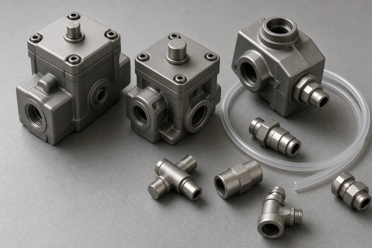
A cylinder that is too small stalls the station, and a cylinder that runs too fast damages the stop at the end of the stroke. Write the load, the pressure at the work port, the stroke and the mount before you pick a bore.
This page is based on public documents, not a test by this site. The worked numbers below are from Josh Cosford’s “A designer’s guide to pneumatic cylinders” (Pneumatic Tips, published 26 January 2026). The research-library copy was fetched on 9 October 2026 and read again on 15 October 2026. They are an example in that article. They are not a rating for your machine.
The pneumatics section is the shelf this note sits on. Air cleanliness is a separate job, on the air preparation note. Whether the motion should be air or a servo is on the comparison.
The four inputs
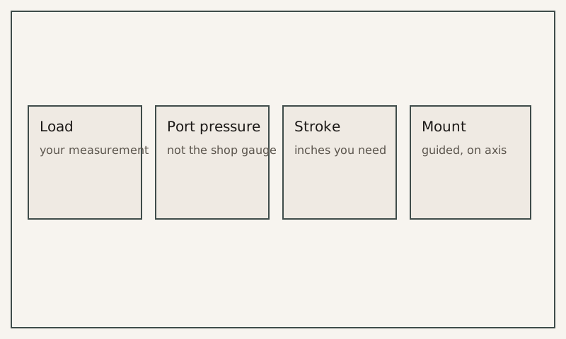
Cosford starts with static force, which he describes as the mass of the load you are moving. For a vertical lift he uses bore diameter, force and the pressure differential across the piston. In his example a 500 pound load and 100 psi shop air produce a calculated bore of 2.52 inches. He says that is slightly larger than the 2.5 inch size typical in North America, so the next bore in that example is 3.25 inches.
A sideways push on a carton is not that vertical lift. Copy your own load into the first box. Leave the bore blank until the pressure at the port is known.
Pressure at the port is lower than shop pressure
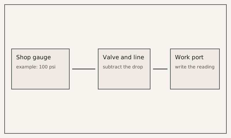
He writes that compressor supply pressure is not available in full at the actuator. Subtract the drop through the valve and the airlines, then subtract the pressure at the opposing work port. Metering out restricts air leaving the cylinder and creates that back pressure. He gives no single figure for it, because it depends on speed, the flow-control setting and the load.
For the bore estimate in the same example he uses a 20 to 40 percent pressure loss, takes the mean of 30 percent, and treats 100 psi shop air as 70 psi for a dynamic load. He then says a 3.25 inch bore can still lift 580 pounds at 70 psi, which he calls marginal, with acceleration that will not be rapid.
If you have gauges on the work ports, write those readings. If you do not, leave the cell empty. This page does not run the bore formula for you, and it has no calculator.
Stroke, seals and speed
A stroke longer than about thirty inches, in his account, disqualifies many designs because those cylinders are limited in stroke. Cycle time includes acceleration and cushioning. He writes that a U-cup seal can be expected to run at over 20 inches per second, while an O-ring cylinder might cap at half that speed, and sometimes slower. Past the velocity the design allows, the seals wear first. More speed means more friction, heat, and then a piston that hits the head or the cap.
One of his airflow formulas multiplies piston area, stroke and cycles per minute, uses 0.7 because he assumes only 70 percent of the cycle time remains once acceleration is included, and divides by 1,728 cubic inches per cubic foot. The formula is in his article. It is not evaluated here.
The mount has to follow the load
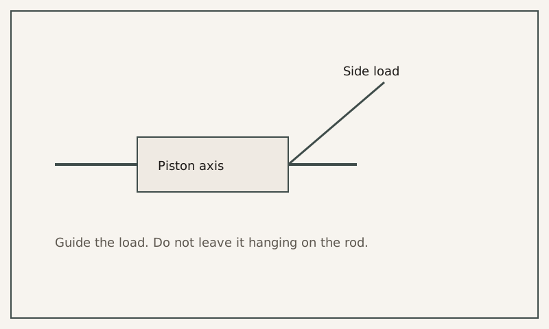
Cosford writes that side load wears a cylinder early. Pivot mounts at the cap, such as a rear clevis or a rear eye, lengthen the column. He names flange mounts as the strongest fixed option when they exist, and the head trunnion as the strongest pivot. Air compresses, so he says a pilot-operated check valve will not hold a load the way it can in a hydraulic circuit. A rod lock has to clamp the rod when the load must stay put.
ISO 21287 appears in the same article as a compact, square-body construction. That is a standard name on a public page. It is not a part number issued by this site. How to match an old number to a document you hold is on the legacy note.
What you still measure
Put your load, your port pressure and your stroke on a sheet. The 500 pound load, the 100 psi shop air, the 2.52 inch calculation, the 3.25 inch bore and the 580 pounds at 70 psi belong to that published example. A leak at the valve changes the port pressure before any of those figures matter. The walk-down for leaks is the survey plan.