A rodless pneumatic cylinder moves an external carriage along its closed barrel without an extending piston rod, keeping installed length close to working stroke while delivering equal thrust in both directions. Choose magnetically coupled designs for leak-free containment on lighter strokes, and pick mechanically slotted band cylinders when heavier loads or deceleration forces would uncouple magnets.
Engineers typically move from a conventional rodded actuator to a rodless slide once long stroke lengths create machine-guard clearance problems or column buckling risks. Record your base load, port pressure, stroke, and mounting inputs first using the cylinder selection questions worksheet in the pneumatics reference section. For standard rodded bore-force equations and free-air demand, see the double acting pneumatic cylinder force and air consumption guide, and for legacy rodded cylinder envelope conversions, see legacy cylinder mounting dimension conversions.
What Is a Rodless Pneumatic Cylinder and How Is the Carriage Coupled?
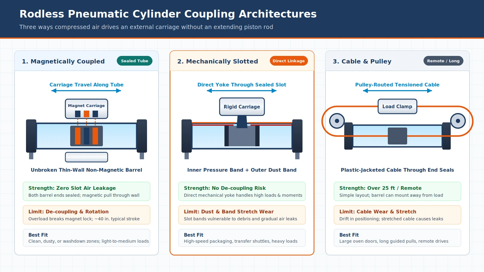
A rodless pneumatic cylinder is a linear air actuator with no extending piston rod that transfers thrust from an internal piston to an external carriage or table moving along the cylinder body without extending beyond it. Coupling follows three distinct mechanical architectures: a longitudinal slotted band, magnetic attraction across a sealed wall, or a pulley-routed cable.
On a conventional double-acting cylinder, the piston rod extends outward past the barrel, making the rod more vulnerable to buckling and bending as stroke grows. According to the Wikipedia pneumatic cylinder reference, once a piston rod length exceeds 10 times its diameter, the rod must be treated as a column and evaluated for buckling. Eliminating the rod removes column buckling and keeps the entire travel envelope contained inside the barrel length; for example, a 25 mm diameter rodless cylinder with a 1,000 mm working stroke occupies only 1,200 mm of machine space whether opened or closed.
| Coupling Architecture | Barrel Enclosure and Seal Path | Force and Coupling Behavior | Typical Stroke and Layout Boundary | Primary Failure Mode to Guard Against |
|---|---|---|---|---|
| Mechanically Slotted Band | Closed end caps with a longitudinal barrel slot sealed by inner and outer flexible metal bands | Direct mechanical yoke between piston and carriage with equal bidirectional thrust and no magnetic de-coupling | Compact overall length equal to working stroke plus end dead lengths; supports high loads and moments | Environmental dust and debris ingress plus sealing-band stretch wear causing air leaks and pressure loss |
| Magnetically Coupled | Completely sealed thin-walled non-magnetic barrel with both ends closed and zero slot openings | Internal magnet pulls external magnetic carriage across solid barrel wall with equal bidirectional thrust | Typically reaches strokes up to about 40 inches in standard layouts with leak-free containment | Magnetic de-coupling when acceleration or load inertia exceeds holding force, plus external carrier rotation |
| Cable and Pulley | Barrel retains openings at one or both ends for a smooth plastic-jacketed flexible cable | Tensioned cable links internal piston around end pulleys to pull an external clamp or carrier | Can exceed 25 feet of stroke and allows the cylinder barrel to mount remotely from the moving load | Cable wear causing inconsistent positioning and stretched cables introducing end-seal air leaks |
How Does a Rodless Air Cylinder Work Internally?
Compressed air alternates into end-cap ports on opposite sides of a long internal piston inside a sealed barrel, driving the piston and attached external carriage linearly in either direction. Because no piston rod blocks either piston face, theoretical output force stays identical on both travel strokes, unlike rodded cylinders whose instroke area is reduced.
A double-acting cylinder requires two working air ports to power both travel directions. In the UNC Charlotte pneumatics engineering toolkit, controlling a double-acting cylinder calls for a five-port directional valve: one port for the air compressor supply, two working ports feeding the cylinder chambers, and two exhaust ports. Compare de-energized center behaviors in five-port directional valve center configurations and exhaust speed control in pneumatic flow control valve meter-in vs meter-out.
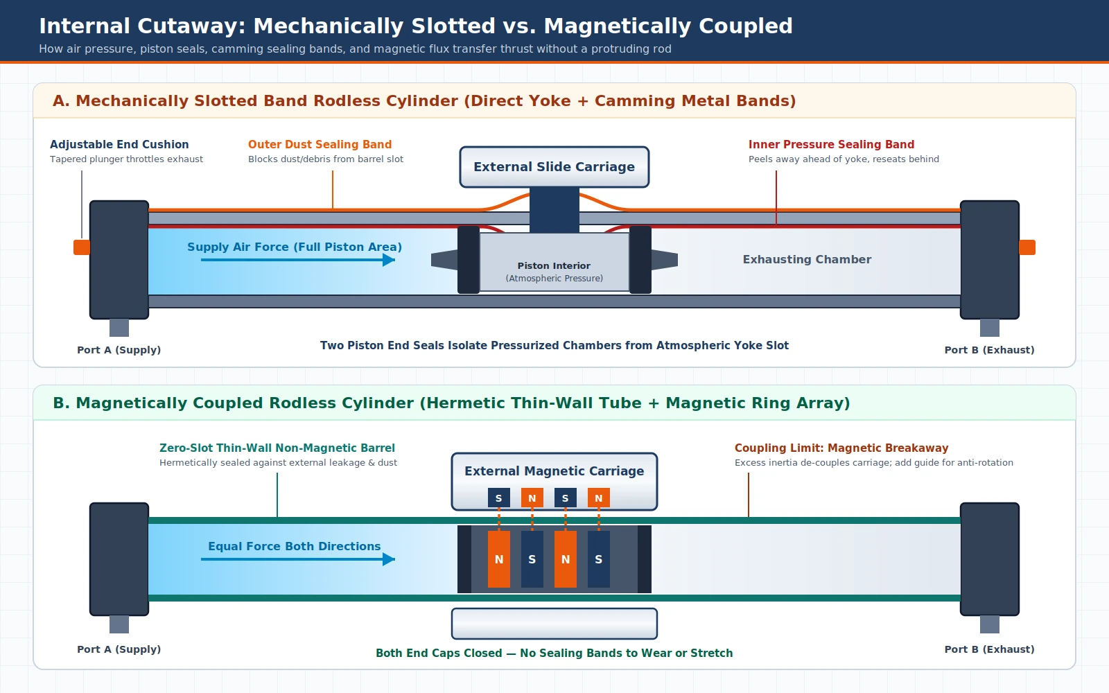
Mechanically slotted working principle
In a mechanically slotted rodless cylinder, a structural yoke extends from the center of the piston to the outside carriage through a narrow slot cut along the length of the cylinder tube. Flexible metal sealing bands close that slot on the inside to stop compressed gas from escaping and on the outside to keep contaminants out. The piston carries two end seals that isolate the pressurized chambers from the center yoke zone, while internal camming surfaces peel the sealing bands away ahead of the projecting linkage and press them back into place behind it, leaving the interior of the piston at atmospheric pressure.
Magnetically coupled working principle
In a magnetically coupled rodless cylinder, both ends of the cylinder are closed off and the tube wall remains completely unbroken with no longitudinal slot. The barrel is built from a thin-walled non-magnetic material so magnetic flux passes cleanly across the tube wall, allowing a powerful internal piston magnet to pull an external magnetic traveller along the exterior of the barrel.
Cable-cylinder working principle
A cable rodless cylinder keeps sealed openings at one or both cylinder end caps so a flexible cable coated with a smooth plastic jacket can exit the piston and wrap around external pulleys. Because a single cable transmits pull rather than compression, it must remain in tension to draw the external clamp left or right without slack.
What Are the Main Rodless Pneumatic Cylinder Parts and Seals?
Every rodless pneumatic cylinder centers on five core assemblies: the barrel, an internal piston with end seals, the coupling and sealing interface, end-cushioning caps, and an external slide carriage. Supporting hardware such as foot mounts, center barrel brackets, and proximity limit switches stabilizes long strokes and detects end positions during cycling.
Barrel material selection depends on load, humidity, temperature, and stroke length, spanning nickel-plated brass, aluminum, steel, and stainless steel across pneumatic cylinder families. Near the end of each stroke, cushion-end air cylinders regulate exhaust air to avoid hard impacts against the cylinder end cover. As the UNC Charlotte pneumatics toolkit explains, deceleration starts when a tapered plunger on the piston enters an opening in the end cap, closing the main outlet so remaining exhaust air must throttle through a restricted passage.
| Component | Mechanical Role Inside the Actuator | Inspection and Wear Boundary |
|---|---|---|
| Cylinder Tube or Barrel | Contains pressurized air chambers and guides internal piston travel across the working stroke | Match alloy to load, humidity, and temperature; keep magnetic tubes thin-walled and non-magnetic |
| Internal Piston and Two End Seals | Separates opposing air chambers and transfers pressure into linear thrust | Check stationary cross-chamber air blow-by because internal leaks lower usable output pressure |
| Inner Pressure and Outer Dust Sealing Bands | Seal the longitudinal slot on mechanically coupled designs against air escape and external contamination | Monitor for stretching and wear over time, since worn bands cause air leaks and pressure drop |
| External Carriage or Shuttle | Mounts directly above or around the barrel to carry and guide the payload along the cylinder axis | Verify carriage bearing capacity against roll, pitch, yaw, and dynamic stopping moments |
| End-Cushioning End Caps | House air ports and tapered-plunger exhaust throttling to slow the piston before hard stops | Tune cushioning to true impact velocity; add external shock absorbers when kinetic energy exceeds limits |
| Foot Mounts, Center Supports, and Limit Switches | End foot mounts stop pivoting, center brackets distribute long-stroke centerline loads, and limit switches sense carrier position | Add center mounting brackets on long strokes to keep the barrel aligned and prevent deflection |
Magnetic vs Slotted vs Cable: When Should You Pick Each Design?
Select a magnetically coupled cylinder when zero external slot leakage and dust exclusion outweigh peak force, pick a mechanically slotted band cylinder when heavy loads, high moments, or fast stops would break magnetic hold, and reserve cable cylinders for specialty strokes exceeding 25 feet or remote barrel placement.
When magnetically coupled cylinders fit best
Magnetically coupled cylinders eliminate the barrel slot entirely, giving engineers a leak-free closed tube with no inner or outer sealing bands to stretch or trap debris. That hermetic enclosure suits clean environments, dusty processes, or light-to-medium transfer stations where strokes stay within roughly 40 inches. Always verify that acceleration, deceleration, and jam loads remain safely below magnetic holding force to prevent de-coupling, and provide external guidance wherever load geometry could twist or rotate the magnetic carriage around the circular barrel.
When mechanically slotted band cylinders fit best
Mechanically slotted cylinders provide a rigid metal connection between piston and carriage so shock loads and fast cycle stops cannot decouple the payload from the piston. They support higher loads and bending moments across compact long strokes, making them the default choice for heavy industrial transfer, cutting, and high-throughput packaging stations. Their trade-off lies at the barrel slot: airborne dust and abrasive debris attack the outer strip, and repeated flexing causes inner and outer sealing bands to stretch and wear over time, eventually allowing air leaks that reduce operating pressure.
When cable rodless cylinders fit best
Cable cylinders solve layout constraints that neither slotted nor magnetic barrels can match cleanly. Because the plastic-jacketed cable routes around pulleys, strokes can exceed 25 feet and the pressurized cylinder tube can be mounted remotely away from hot or crowded zones such as large oven doors. Avoid cable drives where tight repeatability or zero seepage is mandatory, because cable wear degrades positioning consistency and cable stretch can open leaks at the end seals.
How Do Bending Moments, Cushioning, and Vertical Mounting Govern Sizing?
Proper pneumatic cylinder sizing for a rodless axis goes well beyond bore thrust: engineers must verify working stroke plus dead length, evaluate combined roll, pitch, and yaw bending moments, size cushions to true final impact velocity, sum breakaway and friction forces, and add mechanical locks for sustained vertical holding.
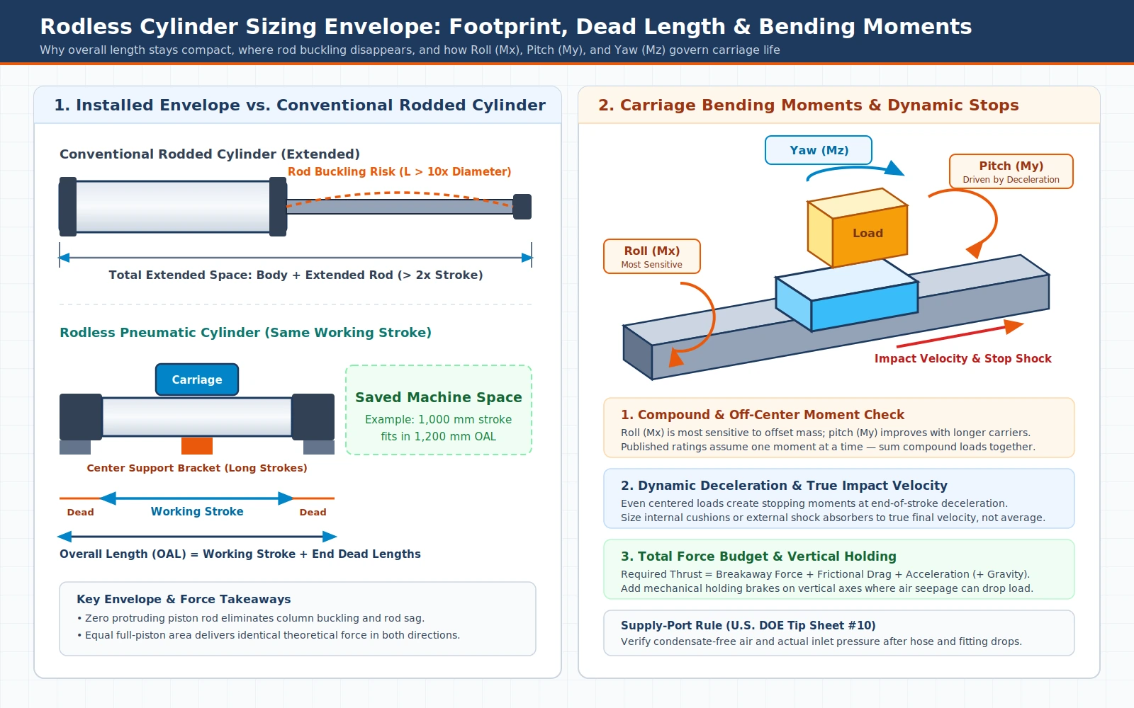
Working stroke, dead length, and overall length
Part of every rodless barrel cannot serve as usable travel because internal piston length and end-of-stroke clearances occupy space at both ends. This unusable portion is the actuator dead length. To confirm machine fit, specify overall length as working stroke plus the published dead length at each end, plus any extra spacing required by auxiliary carriers.
Static and dynamic bending moments (Roll, Pitch, and Yaw)
Off-center payloads generate rotational moments around the carriage axes that grow directly with the distance between the load center of mass and the carrier center:
- Roll (Mx) acts around the travel axis from side-offset loads; rodless carriages are very sensitive to roll moments.
- Pitch (My) acts forward and backward along the travel axis; carriages handle pitch well, especially with longer carriers, though acceleration and deceleration forces directly drive pitch loading.
- Yaw (Mz) twists the carriage horizontally from side-offset inertial or process forces.
Published bending-moment ratings normally assume only one applied moment at a time, so compound loading combining two or more axes must be evaluated together. Crucially, even a load centered directly over the carriage creates dynamic bending moments during acceleration and end-of-stroke deceleration; ignoring those stopping moments shortens bearing life and accelerates seal wear.
Impact velocity, force budget, vertical holding, and port air quality
Internal end cushions must be sized against true final impact velocity rather than average stroke velocity. Whenever stopping moments or deceleration forces exceed the internal cushion rating, fit external shock absorbers or choose a higher-moment carriage. When sizing bore force, remember that total required thrust equals the sum of breakaway force (minimum force to move an unloaded rodless cylinder), frictional drag, and acceleration force, plus gravity when lifting vertically.
On vertical axes, gravity acts both during motion and while holding position. Because some pneumatic rodless designs can seep air and leakage drops holding pressure, do not rely solely on trapped air for extended vertical holding; specify a mechanical lock or holding brake as a safety mechanism against air supply loss or pressure fall. Finally, follow the U.S. Department of Energy compressed-air efficiency tip sheet: do not confuse maximum allowable pressure with required operating pressure, keep supply air free of condensate, and monitor pressure directly at the actuator inlet because improperly sized hoses, fittings, and quick disconnects cause large pressure drops. Check branch-line sizing in tubing inside diameter and pressure drop limits and upstream filtration in air preparation for packaging lines.
| Sizing Variable | Engineering Check Required | Consequence of Skipping the Check |
|---|---|---|
| Overall Length and Dead Length | Add working stroke, both end dead lengths, and any auxiliary carrier spacing | Barrel interferes with machine guarding or falls short of required travel |
| Combined Moment Loading | Sum Roll (Mx), Pitch (My), and Yaw (Mz) ratios for off-center and compound loads | Premature carriage bearing wear, binding, and slotted band distortion |
| True Impact Velocity | Evaluate end-of-stroke final velocity rather than average cycle speed | Excess dynamic stopping moment, end-cap impact damage, or magnetic de-coupling |
| Total Thrust Budget | Sum breakaway force, frictional drag, acceleration force, and vertical gravity | Sluggish start-up, motion lag, or mid-stroke stalling at minimum inlet pressure |
| Vertical Load Holding | Pair pressurized actuation with a mechanical lock or brake where air seepage risks drift | Gradual load drop during dwell or sudden fall upon air supply loss |
| Port Pressure and Air Quality | Measure condensate-free air pressure at the cylinder inlet after hoses and fittings | Reduced output force, seal swelling or wear, and wasted compressor energy |
Which Applications Fit Rodless Cylinders, and How Are Symbols Read on Circuit Diagrams?
Rodless pneumatic cylinders fit tight-envelope linear transfer across packaging, printing, automotive, cutting, material transfer, assembly, robotics, electronics manufacturing, food and beverage production, and pharmaceuticals. On machine schematics, fluid-power symbols follow ISO 1219-1:2012 while full pneumatic circuit diagrams follow ISO 1219-2:2012.
Because compressed air is a gas, cylinder leakage does not drip liquid oil onto surrounding products, making pneumatic rodless drives attractive wherever cleanliness is essential. Where long-stroke axes also demand programmable multi-point stopping or frequent recipe changeovers, weigh air drives against electric linear axes in pneumatic vs electric actuator TCO and changeover.
When reading or issuing pneumatic schematics, two companion standards from the International Organization for Standardization define symbol grammar and diagram layout without conflating component drawings with circuit assembly rules:
- ISO 1219-1:2012 establishes basic symbol elements and rules for devising fluid-power graphical symbols on components and in circuit diagrams. It is a collective application standard of the ISO 14617 series with fixed-dimension symbols built for data-processing systems, which can produce minor graphical variants across CAD libraries. Last reviewed and confirmed in 2026, this version remains current.
- ISO 1219-2:2012 (whose published abstract references ISO 1219-2:2011 rules) sets the main rules for drawing hydraulic and pneumatic circuit diagrams using graphical symbols drawn in accordance with ISO 1219-1. Last reviewed and confirmed in 2023, this edition also remains current.
On an ISO 1219 circuit diagram, trace the rodless cylinder’s two opposing end ports back to a five-port directional control valve (one compressor supply port, two cylinder working ports, and two exhaust ports), verify end-cushion arrows where adjustable cushioning is fitted, and confirm any separate mechanical lock or limit-switch interlock on vertical axes.
Long-Stroke Rodless Selection Handoff Checklist
Before ordering a rodless pneumatic cylinder or releasing a station layout to fabrication, confirm these seven engineering checks:
- Envelope and dead length: Record required working stroke, add end dead lengths and any auxiliary carrier spacing, and verify clearance along the entire barrel.
- Coupling and sealing boundary: Pick magnetically coupled for leak-free closed-tube operation within typical magnetic stroke limits and light-to-medium inertia, mechanically slotted for heavy loads and zero de-coupling risk, or cable for remote mounting and strokes past 25 feet.
- Bending moments and guidance: Quantify Roll (Mx), Pitch (My), and Yaw (Mz) from offset payloads and end-of-stroke deceleration, combine compound loads, and add external anti-rotation guidance on magnetic carriages.
- Long-stroke barrel support: Specify foot mounts at both ends to prevent pivoting and center mounting brackets along long strokes to distribute centerline forces evenly.
- Cushioning and impact speed: Size internal adjustable end cushions or external shock absorbers to true final impact velocity rather than average cycle speed.
- Thrust budget and vertical holding: Verify that available port pressure covers breakaway force, friction, acceleration, and gravity, and add mechanical holding locks whenever vertical loads must remain stationary.
- Inlet air quality and circuit documentation: Deliver condensate-free air, measure actual inlet pressure downstream of hoses and fittings, and document the five-port valve and cylinder symbols to ISO 1219-1:2012 and ISO 1219-2:2012.