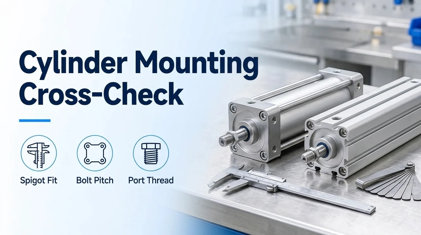
ISO 15552 was prepared by Technical Committee ISO/TC 131, Fluid power systems, Subcommittee SC 3, Cylinders, and the first edition of ISO 15552 cancels and replaces ISO 6431:1992. The second edition cancels and replaces the first edition (ISO 15552:2004), which has been technically revised, and the port size for each piston bore diameter was added to Basic dimensions. This document establishes a metric series of basic, mounting, and accessories dimensions for interchangeability of single or double rod pneumatic cylinders with detachable mountings for a maximum rated pressure of 1 000 kPa (10 bar).
Before removing an existing actuator from the machine frame, write the document title, the date printed on it, the language, and any standard the page names, such as ISO 15552 and ISO 21287, following reading legacy part numbers. Before picking a cylinder bore, write the load, the pressure at the work port, the stroke, and the mount as outlined in cylinder selection questions. This reference covers physical mounting geometry, rod-end threads, detachable bracket interfaces, and port thread identification; for actuator thrust sizing and air demand calculations, refer to our separate guide on double-acting pneumatic cylinder force and air consumption.
Standards Lineage: How ISO 6431 and VDMA 24562 Consolidated into ISO 15552
Under Clause 6 Bore sizes, bore sizes AL included in this series in accordance with ISO 3320 are 32, 40, 50, 63, 80, 100, 125, 160, 200, 250, and 320 in millimetres. The tolerances of dimensions dependent on stroke included in the tables apply for strokes up to and including 1 250 mm. Under Clause 9 Product designation codes, a pneumatic cylinder with detachable mountings, mounting type MT 4, bore 80 mm, and stroke 200 mm shall be designated as ISO 15552 – MT 4 – 80×200.
The AirControl datasheet for ISO 15552 (ISO 6431) · vdma 24562 pneumatic cylinder mounting cross-lists the historical and current designations on the same dimensional envelope. In the AirControl profile cylinder table (covering ISO 15552, ISO 6431, and VDMA 24562), the 32 mm bore uses a G1/8” port, M10x1.25 rod thread, 94 ±0.4 mm basic length, 120 mm retracted length, M6 end-cap thread, 12 mm piston rod diameter, 32.5 mm bolt hole pitch TG, 26 mm rod projection WH, 10 mm wrench flat, and 16 mm thread depth BG.
The ISO 15552 standard references companion ISO standards that govern related cylinder features:
- Normative references include ISO 4393 for the basic series of piston strokes, ISO 4395 for cylinder piston rod end types and dimensions, and ISO 16030 for pneumatic ports and stud ends.
- The basic dimensions are given in Tables 2 and 3 and shown in Figures 2 and 3, and the piston rod diameter shall be larger than the thread diameter (KK) to have a shouldered male thread end.
- The connecting port and the cushion adjusting screw are placed on the same side as the port connection, and the cushion adjusting screw has to be located within dimension E.
- Axial dimensions are determined from a theoretical reference point (TRP) that is the point of force transfer from the piston rod to the movable element.
- For a male threaded rod end, the reference point is located on the rod centreline, at the shoulder level, as shown in ISO 6099 Figure 4.
- In ISO 6099, the sign + after letters means that the stroke is to be added, ZM ++ equals ZM plus twice the stroke, and XV +/ equals XV plus half the stroke.
ISO 15552 Table 2 Basic and Mounting Dimensions (Bores 32 mm to 320 mm)
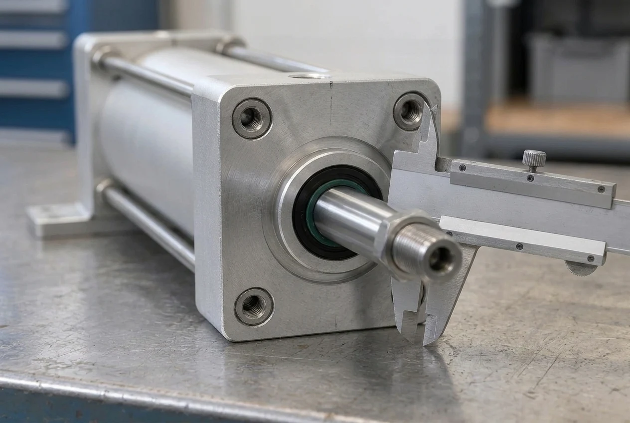
When checking an iso 15552 cylinder bolt pattern table against an existing cylinder on the bench, Table 2 defines the basic dimensions in millimetres across all eleven bore sizes from 32 mm to 320 mm in accordance with ISO 3320:
| Bore | Port | Rod Thread Length A | Spigot BA | Min Depth BG | Max Width E | Rod Thread KK | Body Length | End-Cover Thread RT | Wrench SW | Bolt Pitch TG | Spigot Proj VA | Rod Proj WH |
|---|---|---|---|---|---|---|---|---|---|---|---|---|
| 32 | G1/8” | 22 | 30 | 16 | 50 | M10 × 1,25 | 94 ±0,4 | M6 | 10 | 32,5 ±0,5 | 4 | 26 ±1,4 |
| 40 | G1/4” | 24 | 35 | 16 | 58 | M12 × 1,25 | 105 ±0,7 | M6 | 13 | 38 ±0,5 | 4 | 30 ±1,4 |
| 50 | G1/4” | 32 | 40 | 16 | 70 | M16 × 1,5 | 106 ±0,7 | M8 | 17 | 46,5 ±0,6 | 4 | 37 ±1,4 |
| 63 | G3/8” | 32 | 45 | 16 | 85 | M16 × 1,5 | 121 ±0,8 | M8 | 17 | 56,5 ±0,7 | 4 | 37 ±1,8 |
| 80 | G3/8” | 40 | 45 | 17 | 105 | M20 × 1,5 | 128 ±0,8 | M10 | 22 | 72 ±0,7 | 4 | 46 ±1,8 |
| 100 | G1/2” | 40 | 55 | 17 | 130 | M20 × 1,5 | 138 ±1 | M10 | 22 | 89 ±0,7 | 4 | 51 ±1,8 |
| 125 | G1/2” | 54 | 60 | 20 | 157 | M27 × 2 | 160 ±1 | M12 | 27 | 110 ±1,1 | 6 | 65 ±2,2 |
| 160 | G3/4” | 72 | 65 | 24 | 195 | M36 × 2 | 180 ±1,1 | M16 | 36 | 140 ±1,1 | 6 | 80 ±2,2 |
| 200 | G3/4” | 72 | 75 | 24 | 238 | M36 × 2 | 180 ±1,6 | M16 | 36 | 175 ±1,1 | 6 | 95 ±2,2 |
| 250 | G1” | 84 | 90 | 25 | 290 | M42 × 2 | 200 ±1,6 | M20 | 46 | 220 ±1,5 | 10 | 105 ±2,2 |
| 320 | G1” | 96 | 110 | 28 | 353 | M48 × 2 | 220 ±2,2 | M24 | 55 | 270 ±1,5 | 10 | 120 ±2,2 |
Catalog Cross-Check: Comparing Published ISO 15552 / VDMA 24562 / ISO 6431 Series
AirControl Profile and Tie-Rod Cylinder Tables
In the AirControl technical datasheet for ISO 6431, ISO 15552, and VDMA 24562 pneumatic cylinders, the profile cylinder table lists the standard dimensions by bore:
| Bore | Spigot BA | Width E | Port | Rod Thread KK | Body Length | Retracted Length | End-Cap Thread RT | Rod Dia | Bolt Pitch TG | Rod Proj WH | Wrench SW | Thread Depth BG |
|---|---|---|---|---|---|---|---|---|---|---|---|---|
| 32 | 30 | 47 | G1/8” | M10x1.25 | 94 ±0.4 | 120 | M6 | 12 | 32.5 | 26 | 10 | 16 |
| 40 | 35 | 53 | G1/4” | M12x1.25 | 105 ±0.7 | 135 | M6 | 16 | 38 | 30 | 13 | 16 |
| 50 | 40 | 65 | G1/4” | M16x1.5 | 106 ±0.7 | 143 | M8 | 20 | 46.5 | 37 | 16 | 16 |
| 63 | 45 | 75 | G3/8” | M16x1.5 | 121 ±0.8 | 158 | M8 | 20 | 56.5 | 37 | 16 | 16 |
| 80 | 45 | 95 | G3/8” | M20x1.5 | 128 ±0.8 | 174 | M10 | 25 | 72 | 46 | 21 | 16 |
| 100 | 55 | 115 | G1/2” | M20x1.5 | 138 ±1 | 189 | M10 | 25 | 89 | 51 | 21 | 16 |
For large tie-rod cylinders in the AirControl ISO 15552 and VDMA 24562 series, the datasheet specifies:
- For bore 160 in the tie-rod cylinder table, port is G3/4“, rod thread length is 72, square width is 180, rod thread is M36x2, retracted length is 260±1,7, piston rod diameter is 40, bolt hole pitch TG is 140, rod projection WH is 80, wrench flat is 34, end-cap thread is M16, BG is 21, VA is 6, and spigot diameter BA is 65.
- For bore 200 in the tie-rod cylinder table, port is G3/4“, rod thread length is 72, square width is 220, rod thread is M36x2, retracted length is 275±1,7, piston rod diameter is 40, bolt hole pitch TG is 175, rod projection WH is 95, wrench flat is 34, end-cap thread is M16, BG is 22, VA is 6, and spigot diameter BA is 75.
- For bore 250 in the tie-rod cylinder table, rod thread length is 84, square width is 275, port is G1“, rod thread is M42x2, retracted length is 305±2, piston rod diameter is 50, bolt hole pitch TG is 220, rod projection WH is 105, wrench flat is 46, end-cap thread is M20, BG is 25, VA is 9, and spigot diameter BA is 90.
- For bore 320 in the tie-rod cylinder table, rod thread length is 96, square width is 344, port is G1“, rod thread is M48x2, retracted length is 340±2, piston rod diameter is 63, bolt hole pitch TG is 270, rod projection WH is 120, wrench flat is 55, end-cap thread is M24, BG is 28, VA is 9, and spigot diameter BA is 110.
Almotion / Pneumax AMA and AMT Series Cylinder Table
In the Almotion / Pneumax AMA and AMT Series catalog, the standard dimensions table lists:
| Bore (mm) | Rod Thread Length AM (mm) | Spigot B (mm) | Thread Depth BG (mm) | Square Width E (mm) | Port EE | Rod Thread KK | Neck Length (mm) | Cap-to-Head Length (mm) | Nut Height H (mm) |
|---|---|---|---|---|---|---|---|---|---|
| 32 | 22 | 30 | 15 | 47 | 1/8“ | M10x1,25 | 20 | 94 | 6 |
| 40 | 24 | 35 | 15 | 52 | 1/4“ | M12x1,25 | 22 | 105 | 7 |
| 50 | 32 | 40 | 16 | 65 | 1/4“ | M16x1,5 | 26 | 106 | 8 |
| 63 | 32 | 45 | 16 | 75 | 3/8“ | M16x1,5 | 25 | 121 | 8 |
| 80 | 40 | 45 | 17 | 95 | 3/8“ | M20x1,5 | 32 | 128 | 9 |
| 100 | 40 | 55 | 17 | 115 | 1/2“ | M20x1,5 | 38 | 138 | 9 |
| 125 | 54 | 60 | 21 | 140 | 1/2“ | M27x2 | 40 | 160 | 12 |
For the 125 mm bore in the second row of the Almotion standard dimensions table, piston rod diameter MM is 32 mm, L7 is 27,5 mm, PL is 23 mm, end-cap thread RT is M12, bolt hole pitch TG is 110 mm, VA is 5 mm, VD is 5 mm, rod projection WH is 65 mm, wrench flat is 27 mm, rod nut wrench size is 41 mm, and nut height is 12 mm.
Port Thread Verification: BSP Parallel (G), BSPT Tapered, Metric, and NPT
Under Clause 6 Bore sizes in ISO 6432, miniature cylinder bore sizes AL in accordance with ISO 3320 are 8, 10, 12, 16, 20, and 25 in millimetres. In ISO 6432:2015 Table 1, miniature bores 8 mm and 10 mm use metric M5 ports and M4 rod threads, bore 12 mm uses M5 ports and M6 rod threads, while bores 20 mm and 25 mm use G1/8 ports with M8 and M10 × 1,25 rod threads (with E max 34 mm and D max 40 mm).
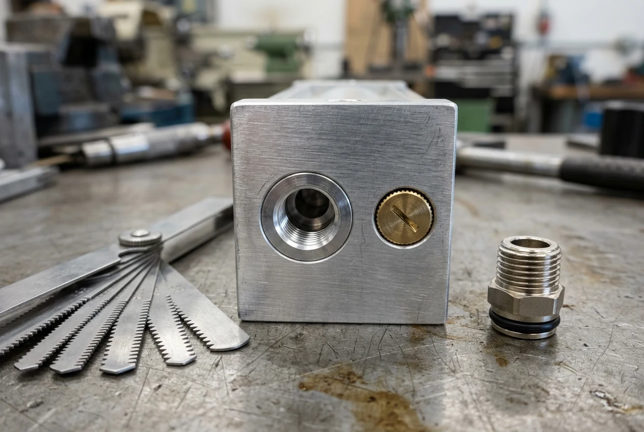
For pneumatic ports and stud ends, ISO 16030 specifies parallel G series threads and reusable positively retained seals for −0,09 MPa (−0,9 bar) up to 1,6 MPa (16 bar), and warns they are not intended to connect with ISO 1179 ports (ISO 1179-1) or ISO 7-1 threads. Ports, stud ends, and sealing devices shall be designed for use within a rated temperature range from −20 °C to +80 °C unless otherwise specified.
Thread Form Geometry and Compatibility Rules
- ISO 228 parallel threads: The internal and external threads covered by this part of ISO 228 are both parallel.
- DIN-EN-ISO 228-1 flank angle: G-threads have a parallel shape in accordance with the DIN-EN-ISO 228-1 standard with a flank angle of 55 degrees.
- BSPT tapered threads: Characteristics of BSPT taper threads include rounded roots and crests, a 55 degree thread angle, and a taper of 3/4“ per foot or 1 in 16 on the diameter.
- NPT vs. ISO thread incompatibility: NPT has a taper rate of 1 in 16 inch (3/4 inch in a foot or 62.5 mm in a meter) and a 60 degree angle versus 55 degrees for ISO threads, so ISO and NPT threads should not be mixed.
Caliper and Pitch Gauge Reference Data
Measure the port thread outside diameter and thread count per inch (TPI) or pitch against the reference values from The Engineering ToolBox tables below:
- ISO 228 G 1/8 to G 1/2 dimensions: In the ISO 228 pipe thread table, G 1/8 has 9.73 mm outside diameter (8.85 mm / 8.80 mm), 28 TPI, and 0.907 mm pitch; G 1/4 has 13.16 mm outside diameter (11.89 mm / 11.80 mm), 19 TPI, and 1.337 mm pitch; G 3/8 has 16.66 mm outside diameter (15.39 mm / 15.25 mm), 19 TPI, and 1.337 mm pitch; and G 1/2 has 20.95 mm outside diameter (19.17 mm / 19.00 mm), 14 TPI, and 1.814 mm pitch.
- ISO 228 G 3/4 and G 1 dimensions: In the ISO 228 pipe thread table, G 3/4 has 26.44 mm outside diameter (24.66 mm / 24.50 mm), 14 TPI, and 1.814 mm pitch, while G 1 has 33.25 mm outside diameter (30.93 mm / 30.75 mm), 11 TPI, and 2.309 mm pitch.
- ANSI B1.20.1 NPT 1/8“ to 1/2“ dimensions: In the ANSI B1.20.1 NPT table, 1/8“ has 27 TPI and 0.405 inch OD; 1/4“ has 18 TPI and 0.540 inch OD; 3/8“ has 18 TPI and 0.675 inch OD; and 1/2“ has 14 TPI and 0.840 inch OD.
Detachable Mounting Accessories and Profile vs. Tie-Rod Barrel Swaps
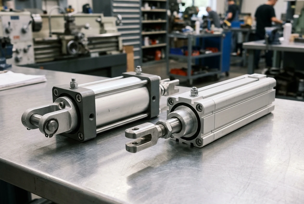
Detachable Cylinder and Rod-End Mounting Accessory Dimensions
- ISO 6099 mounting types: ISO 15552 includes mounting types described in ISO 6099: MF1 (Head, rectangular flange), MF2 (Cap, rectangular flange), MP2 (Cap, detachable clevis), MP4 (Cap, detachable plain eye), MP6 (Cap, detachable eye with spherical bearing), MS1 (End angles), and MT4 (Intermediate trunnion).
- Rear clevis bracket pin hole diameters: For rear clevis brackets in the AirControl datasheet, the pin hole diameter (H9) is 10 for bore 32 (M10X1,25), 12 for bores 40 (M12X1,25) and 50 (M16X1,5), 16 for bore 63 (M16X1,5) and bore 80 (M20X1,5), and 20 for bore 100.
- Intermediate trunnion pin diameters: For intermediate trunnions in the AirControl datasheet, the trunnion pin diameter (e9) is 12 for bore 32 (M10x1.25), 16 for bores 40 (M12x1.25) and 50 (M16x1.5), and 20 for bore 63.
- Rod-end clevis (ISO 8140) scope and dimensions: This International Standard specifies the mounting dimensions required for interchangeability of rod-end clevises designed for 1 000 kPa (10 bar) series cylinders in accordance with ISO 6430, ISO 6432, and ISO 15552. In Table 1 for AP2 rod clevises, thread M10 × 1,25 uses a 10 mm pin diameter (40 mm length, 20 mm, 16 mm); M12 × 1,25 uses a 12 mm pin (48 mm length, 22 mm, 24 mm, 19 mm); M16 × 1,5 uses a 16 mm pin (64 mm length, 28 mm, 32 mm, 25 mm); and M20 × 1,5 uses a 20 mm pin (80 mm length, 33 mm, 40 mm, 32 mm). Under Clause 5.1.1 and Clause 5.1.2, the tolerance of f8 (see ISO 286-2) is recommended for the bearing shaft, and the rod and clevis shall be locked with a locking nut.
- Rod-end spherical eye (ISO 8139) dimensions and shaft tolerances: In Table 1 for AP6 rod-end spherical eyes, M10 × 1,25 has a 10 mm bore and 43 mm length (14 mm, 15 mm, 20 mm); M12 × 1,25 has a 12 mm bore and 50 mm length (16 mm, 17 mm, 22 mm); M16 × 1,5 has a 16 mm bore, 64 mm length (21 mm, 22 mm, 28 mm), and 4 degree tilting angle; and M20 × 1,5 has a 20 mm bore and 77 mm length (25 mm, 26 mm, 33 mm). Usually a tolerance of m6 (see ISO 286-2) is used for the shaft fitting the spherical plain bearing bore, while a tolerance of f7 can be admitted in exceptional cases.
Profile vs. Tie-Rod Barrel Swaps
In the Almotion / Pneumax ISO 15552 catalog, cylinders can be supplied with two different shapes of the barrel: the AMA type with “T” and “C” grooves allowing the flush-mounted magnetic switch, and the AMT type round barrel with tie-rods. When swapping between an AMA profile barrel and an AMT tie-rod barrel of the same bore size, verify whether existing magnetic proximity switches mount flush inside “T” or “C” grooves or require external tie-rod mounting brackets.
Bench Verification Checklist Before Ordering a Replacement Cylinder
- Confirm standard bore size (Clause 6): Check that the nominal cylinder bore AL in accordance with ISO 3320 is 32, 40, 50, 63, 80, 100, 125, 160, 200, 250, or 320 in millimetres.
- Distinguish miniature cylinders (Clause 6): If the nominal bore AL in accordance with ISO 3320 is 8, 10, 12, 16, 20, or 25 in millimetres, the actuator belongs to the miniature cylinder series.
- Check stroke tolerance applicability: Confirm whether the stroke length is up to and including 1 250 mm, where the tolerances of dimensions dependent on stroke included in the tables apply.
- Verify shouldered piston rod end: Check that the piston rod diameter is larger than the male thread diameter (KK) so the rod end forms a shouldered male thread end as shown in Tables 2 and 3 and Figures 2 and 3.
- Check port and cushion screw alignment (Figure 2): Verify that the connecting port and cushion adjusting screw are on the same side as the port connection and that the cushion adjusting screw is located within maximum width E.
- Verify parallel G versus tapered NPT port threads: Measure the port outside diameter and pitch against the ISO 228 table (G 1/8 = 9.73 mm OD at 28 TPI and 0.907 mm pitch; G 1/4 = 13.16 mm OD at 19 TPI and 1.337 mm pitch; G 3/8 = 16.66 mm OD at 19 TPI and 1.337 mm pitch; G 1/2 = 20.95 mm OD at 14 TPI and 1.814 mm pitch). Remember that NPT has a taper rate of 1 in 16 inch (62.5 mm in a meter) and a 60 degree angle versus 55 degrees for ISO threads, so ISO and NPT threads should not be mixed.
- Check rod-end clevis and spherical eye shaft fits: For a rod-end clevis under Clause 5.1.1 and Clause 5.1.2, use the recommended f8 bearing shaft tolerance (see ISO 286-2) and lock the rod and clevis with a locking nut. For a rod-end spherical plain bearing eye, usually use the m6 shaft tolerance (see ISO 286-2), or f7 in exceptional cases.
Sources
- International Organization for Standardization — ISO 15552 First Edition (canceling and replacing ISO 6431:1992)
- International Organization for Standardization — ISO 15552 Second Edition (canceling and replacing ISO 15552:2004)
- AirControl Industrial — Pneumatic Cylinders ISO 15552 (ISO 6431) and VDMA 24562 Technical Datasheet
- Almotion / Pneumax — Pneumatic Cylinders AMA and AMT Series Technical Datasheet
- The Engineering ToolBox — Pipe Thread Reference Tables (DIN-EN-ISO 228-1 Parallel G, BSPT Taper, and NPT Pipe Threads)
- Pneumatics Practice Notes — Legacy Part Numbers and Cylinder Selection Reference Guides