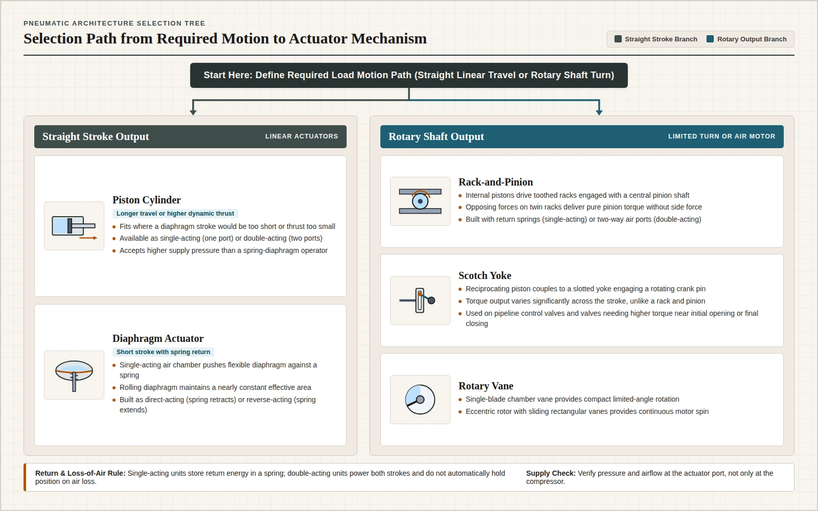
A pneumatic actuator converts compressed air into mechanical motion by expanding air against an enclosed piston or a flexible diaphragm to make a straight stroke, or by driving a toothed rack, a slotted yoke, or an internal vane to make rotation. Use a piston actuator when a diaphragm stroke would be too short or its thrust too small. Use a diaphragm actuator when the stroke is short and a single-acting spring return fits the valve or load.
Industrial compressed-air systems directly serve pneumatic tools, pneumatic controls, and compressed-air-operated cylinders for machine actuation, while process plants also use pneumatic actuators to position air-operated control valves and dampers. Start mechanical layout in the pneumatics reference section and pair the mechanism choice below with the load, port-pressure, stroke, and mounting worksheet in cylinder selection questions. If the axis itself is still being weighed between air and closed-loop electric drive, compare motion duties in pneumatic vs servo motion and ownership economics in pneumatic vs electric actuator TCO and changeover.
How Does a Pneumatic Actuator Convert Air Into Motion?
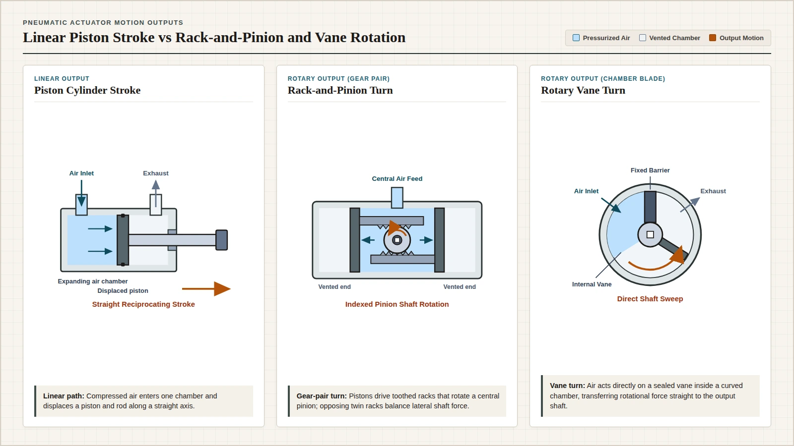
Expanding compressed air transforms stored pneumatic energy into kinetic energy and mechanical work along either a linear or a rotary path. In a pneumatic cylinder (also called an air cylinder), compressed gas enters the tube at one end of the piston, imparts force on the piston face, and displaces the piston and rod in reciprocating linear motion. In a pneumatic control valve actuator, trapped air pressure forces a piston or diaphragm to translate a sliding valve stem or rotate a valve control element. Because the working fluid is a gas, external cylinder leakage does not drip out and contaminate surrounding surfaces where cleanliness is required.
Operating pressures and control signals belong to distinct service categories and should not be merged across equipment families:
- Fluid-power pressure range: In the University of Michigan actuator encyclopedia, hydraulic actuators operate at 100 to 200 bar pressure, whereas pneumatic actuators are typically used up to 7 bar.
- Metric valve control signal: On Wikipedia’s control-valve actuator overview, a typical standard pneumatic control signal is 20-100 kPa.
- Instrument-air valve loop: In an Idaho National Laboratory report on pneumatic valves, the plant instrument air supply is typically 100 psig, while a current-to-pressure (I/P) converter takes a 4 to 20 milliamp electronic signal and modulates a flapper over an air nozzle to vary output air pressure between 3 and 15 psig. A valve positioner then works to hold the commanded valve position for a given input signal despite shifts in valve differential pressure, stem friction, and diaphragm hysteresis.
Port count separates unidirectional return units from two-way powered units. A single-acting cylinder has one port: compressed air moves the piston and rod in one direction, and stored spring energy returns the stem or rod to its original position when air exhausts through that same port. A double-acting cylinder has two ports, one at each end, so alternating air admission drives both the extend outstroke and the retract instroke. Double-acting actuators should not automatically be assumed to hold their last position when air pressure is lost; where air loss or falling pressure could cause damage, mechanical locks can sometimes serve as a separate safety mechanism.
What Are the Main Pneumatic Actuator Types?
Pneumatic actuators divide first into linear and rotary categories, and then by internal sealing and transmission geometry. Across industrial machine cylinders, air motors, and air-operated valves, published classifications list piston with moving rod cylinders (including tie-rod, through-rod, telescoping, and cushion-end cylinders), rodless actuators with magnetic or mechanical linkage, grippers, spring-and-diaphragm operators, quarter-turn or limited-rotation rotary actuators (rack-and-pinion, Scotch yoke, and vane), and continuous-rotation pneumatic motors (vane, piston, air turbine, and gear motors). Among linear machine cylinders in the UNC Charlotte pneumatics toolkit, the most common style uses a piston with a moving rod inside a cylinder barrel.
| Actuator family | Motion output | Internal mechanism | Porting and return options | Primary selection boundary |
|---|---|---|---|---|
| Piston cylinder actuator | Straight reciprocating stroke | Compressed air acts on a solid enclosed piston inside a cylinder tube to displace a rod or stem | Single-acting (one port with spring return) or double-acting (two ports, air in both directions) | Chosen when a diaphragm stroke would be too short or the thrust is too small; check rod buckling, side load, and end cushions |
| Diaphragm actuator | Short straight stem stroke | Differential air pressure flexes a diaphragm (including rolling diaphragms with nearly constant effective area) against a calibrated spring | Single-acting air supply on one side: direct-acting (spring to retract) or reverse-acting (spring to extend) | Suited to short-stroke spring-return valve or damper positioning; limited maximum supply pressure and dynamic force |
| Rack-and-pinion rotary | Limited shaft rotation for valves and machine arms | Internal pistons move linear toothed racks that mesh with a central pinion on the output shaft | Single-acting with return springs or double-acting with air fed to either side of the pistons | Twin opposing racks can deliver pure torque on the pinion without a force component |
| Scotch yoke rotary | Limited rotation (common on pipeline control valves) | Reciprocating piston couples directly to a slotted yoke engaging a pin on the rotating arm | Single-acting with spring return or double-acting cylinder power | Torque output varies significantly across the stroke; yoke slot faces sliding friction and high contact pressure unless mitigated by a sliding block |
| Limited-rotation vane | Indexed shaft turn | Compressed air pushes directly on an internal chamber vane attached to the output shaft | Dual-action chamber porting | Compact chamber layout; a single-blade damper actuator in the UNC Charlotte note reaches a maximum angle of approximately 270 degrees |
| Continuous air motor (vane, piston, turbine, gear) | Continuous shaft rotation | Expanding air drives sliding rectangular vanes in an eccentric rotor, reciprocating pistons, a turbine, or meshing gears | Continuous inlet and exhaust ports | Supplies continuous rotary work rather than a fixed stop angle; gear motors tend to leak at low speeds and suit medium-speed duty |
Piston vs Diaphragm Actuators: Which Linear Design Fits?
Both piston and diaphragm actuators generate straight-line force from air pressure, yet their pressure limits, stroke envelopes, and dynamic thrust reserves separate their jobs cleanly.
In a spring-diaphragm actuator, a flexible diaphragm works against a large return spring set to the pressure needed to hold the diaphragm in place. In the valve arrangement shown by the University of Michigan encyclopedia, raising air pressure below the diaphragm above the pressure in the upper chamber moves the diaphragm upward to open the valve; the Idaho National Laboratory report says that if the air pressure is reduced, the spring moves the valve stem in the opposite direction. Rolling-diaphragm designs maintain a virtually constant effective diaphragm area throughout the actuator stroke; air feeds one side only in single-acting operation, configured as direct-acting (spring to retract) or reverse-acting (spring to extend).
A piston actuator replaces the flexible membrane with a solid enclosed piston inside a rigid cylinder. In the University of Michigan valve-actuator comparison, the air-supply pressure that may be used on a piston actuator is twice the maximum of a spring-diaphragm actuator, and air can be loaded onto or unloaded from the top of the piston to set the valve position. A commercial actuator note says piston actuators are generally used where the stroke of a diaphragm actuator would be too short or the thrust is too small, and an NRC valve-actuator symposium reports that diaphragm actuators, as sized, many times do not supply enough force under dynamic conditions, with one stated remedy being a change to a cylinder actuator that can be used as a single-acting or double-acting unit.
On a double-acting cylinder the stroke length for this design is not limited, but the piston rod is more vulnerable to buckling and bending. Keep bore force, rod-side annular retract force, free-air consumption, and buckling checks together using double-acting pneumatic cylinder force and air consumption.
Rack-and-Pinion, Scotch Yoke, or Vane for Rotary Motion?
When a machine index arm, damper, or quarter-turn valve needs rotation rather than linear push, three limited-rotation mechanisms dominate pneumatic selection: rack-and-pinion, Scotch yoke, and vane actuators. Ball and butterfly valves typically require about 90 degrees of rotation between open and closed positions, whereas damper and material-handling blades can call for wider sweep angles.
Rack-and-pinion actuators
A rack-and-pinion pair converts linear piston displacement into shaft rotation through toothed racks engaged with a central pinion gear. Pressurizing one chamber while exhausting the opposite chamber drives twin pistons apart to turn the pinion counterclockwise, and reversing the pressurized and vented chambers forces the pistons inward to turn the pinion clockwise. Single-acting casings admit air into the central chamber to push the pistons outward against return springs, while double-acting casings omit return springs and admit air on either side. Applying opposite forces to two racks produces pure torque on the pinion without any force component, and this double-rack arrangement can be used with a pair of pneumatic actuators to operate a valve with minimum stress.
Scotch yoke actuators
A Scotch yoke (or slotted-link mechanism) couples a reciprocating piston directly to a sliding yoke whose slot engages a pin on the rotating shaft arm; at constant rotational speed, piston displacement follows a sine wave of constant amplitude and frequency. Widely fitted to control valves on high-pressure oil and gas pipelines, Scotch yoke actuators differ from rack-and-pinion units because their torque output varies significantly throughout the stroke. That variable curve can help valves that demand higher torque near initial opening or final closing, with the exact curve governed by the actuator’s internal geometry. Engineers also account for contact stress inside the yoke: sliding friction and high contact pressures can wear the slot rapidly unless mitigated by a sliding block between the crank pin and slot.
Rotary vane actuators and continuous air motors
A rotary vane actuator applies compressed air directly against an internal vane inside a curved chamber, transferring rotational force to the output shaft. In the UNC Charlotte engineering note, a dual-action limited-rotation actuator built around a single rotating blade on the output shaft reaches a maximum rotation angle of approximately 270 degrees for actuated dampers in robotics and material handling. Keep that 270-degree single-blade limit separate from the 90-degree travel typical of ball and butterfly valves.
Where continuous shaft spin is needed instead of limited angular travel, rotary vane air motors mount a slotted rotor eccentrically inside a housing; springs, cam action, or air pressure extend rectangular vanes to the housing walls while inlet air pushes the vanes and exhausts at the outlet. Gear-type air motors tend to leak internally at low speeds and are therefore often applied in medium-speed drives. Read the manufacturer’s specification sheet for the selected rotary actuator model to confirm its moment-of-inertia limit.
How Are Pneumatic Actuator Symbols and Diagrams Read?
Component nameplates and machine schematics follow two companion ISO standards whose public catalog abstracts define their scope without publishing free symbol sheets.
Published as Edition 3 in 2012, ISO 1219-1:2012 establishes the basic elements and rules for devising fluid-power graphical symbols on components and in circuit diagrams. It serves as a collective application standard of the ISO 14617 series and defines symbols in fixed dimensions for direct use in data-processing systems, which might result in different variants. On the public ISO catalog record, ISO 1219-1:2012 was last reviewed and confirmed in 2026, so this version remains current.
Circuit assembly rules sit on the public catalog page titled ISO 1219-2:2012 (Published Edition 2, 2012, last reviewed and confirmed in 2023, remaining current). Its published abstract states that ISO 1219-2:2011 establishes the main rules for drawing hydraulic and pneumatic circuit diagrams using graphical symbols drawn in accordance with ISO 1219-1, and also applies to circuit diagrams for cooling, lubrication, cooling-lubricant, and technical-gas systems used with fluid power.
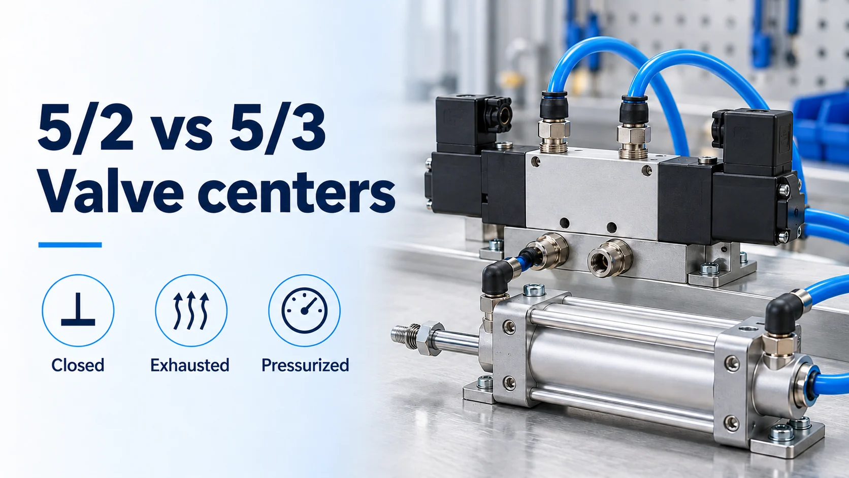
When tracing directional control connections on a schematic, the UNC Charlotte pneumatics note pairs a single-action cylinder with a two-port control path and a double-acting cylinder with a five-port directional valve: one port for the air compressor supply, two working ports for the cylinder chambers, and two exhaust ports. How a three-position directional valve behaves when de-energized (closed, exhausted, or pressurized center) belongs to five-port directional valve center configurations, while exhaust throttling belongs to pneumatic flow control valve meter-in vs meter-out.
How Do You Check Leakage, Sticking, Side Load, and Cushions?
Static thrust tables do not protect an actuator against internal seal bypass, air-line contamination, lateral rod loads, or end-cap impact. Inspect those four boundaries on the assembled machine.
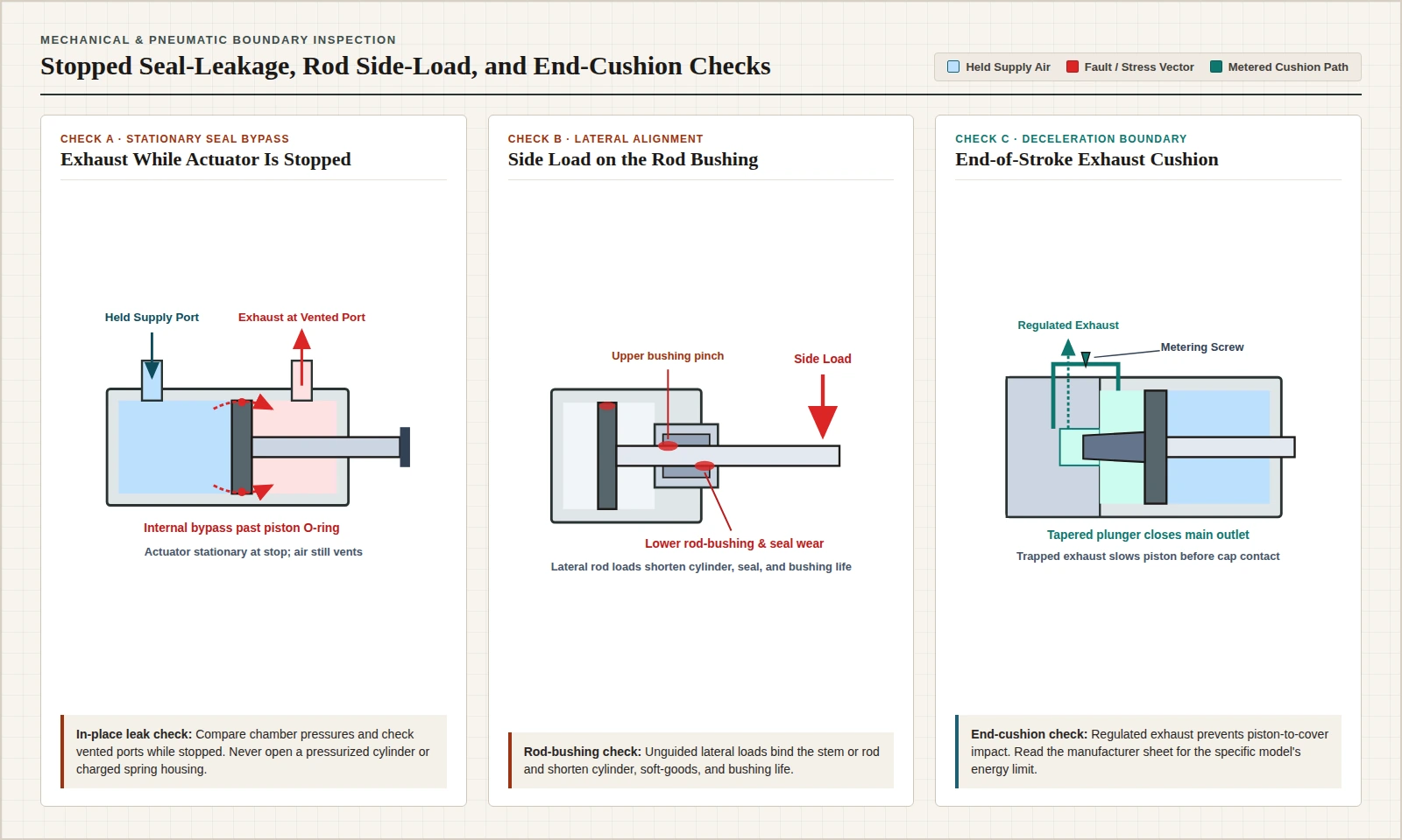
Internal leakage and sticking checks (assembled and in place)
Air leakage from the input or output drops effective actuator pressure, and a worn end use will often require higher pressure, consume excess compressed air, and disturb nearby operations. Routine inspection covers air leaks, external seals and connections, and smooth travel across the stroke.
In NRC symposium testing of a vertically mounted cylinder actuator, significant internal leakage past the piston O-ring was detected directly from the top and bottom cylinder pressures without opening the barrel. The same symposium highlights three diagnostic traps on air-operated valves:
- Air leaks combined with faulty mechanical parts can trigger constant valve cycling.
- Over-tightening a diaphragm actuator housing stresses and warps the upper and lower diaphragm cases and can cut through the diaphragm.
- One leak can mask another: if both a diaphragm casing and a stem bushing leak, the stem-bushing leak may stay hidden until the casing leak is repaired.
Sticking and erratic travel trace back to both mechanical friction and dirty air. Table 1 of the Idaho National Laboratory report lists air leaks, diaphragm failure, spring failure, and stem binding as actuator failure mechanisms, and it lists erratic valve operation among the actuator failure modes; the report cites a nuclear-industry pneumatic review in which 49 percent of failure events resulted from contamination in the system and only 28 percent were attributed to component failures. Dirt or rust can plug tiny I/P converter ports and cause sluggish response, dirt and rust inside an actuator can make a valve stick, foreign material in a cylinder causes leakage or wear, and hydrocarbon contamination deteriorates neoprene or rubber diaphragms. Keep end-use air free of condensate, follow manufacturer lubrication rules where specified, and eliminate mechanical binding of any sort because friction or binding shifts actuator bench set.
Observe strict stored-energy safety during every leak or binding check: never disassemble a cylinder actuator while it is under pressure of any sort, and never assume spring energy is gone when disassembling an actuator.
Side load on the rod bushing and inlet pressure drop
Linear cylinders are built to push and pull along the rod axis. Telescoping cylinders, for example, are primarily utilized where the piston bears minimal side loading. In the NRC symposium, mounting a valve cylinder actuator horizontally rather than vertically creates a significant side-load effect that diminishes the life span of the cylinder, soft goods, and bushings. On industrial machinery where a cylinder runs horizontally or off-axis, verify that external linear guides carry lateral forces so the rod bushing is not loaded sideways.
At the supply port, the U.S. Department of Energy compressed-air tip sheet cautions engineers not to confuse maximum allowable pressure with required operating pressure, and notes that improperly sized hoses, fittings, and quick disconnects often create large pressure drops that cut inlet pressure and tool or actuator output. Verify minimum available pressure and adequate airflow right at the actuator port rather than only at the compressor, and size branch lines with tubing inside diameter and pressure drop limits.
End-of-stroke cushioning
Cushion-end air cylinders regulate air exhaust to prevent mechanical impacts between the piston rod assembly and the cylinder end cover. On double-acting cylinders equipped with internal end cushions, deceleration begins near the end of the stroke when a tapered plunger enters the opening in the cylinder head, closes the main fluid outlet, and restricts the remaining exhaust flow. Because internal cushions absorb axial stroke energy rather than lateral misalignment, read the manufacturer’s specification sheet for the chosen actuator model to check its allowable kinetic energy limit.
Actuator Selection Handoff Checklist
Before finalizing an actuator specification or handing circuit requirements to mechanical layout, record these eight verification items:
- Motion path: Confirm whether the driven mechanism requires a straight reciprocating stroke or a rotary turn (such as an approximately 90-degree quarter-turn ball or butterfly valve, an approximately 270-degree single-blade damper, or continuous air-motor rotation).
- Piston vs diaphragm element: Choose a diaphragm actuator for short single-acting strokes where spring return is enough, or switch to a piston cylinder when diaphragm travel is too short or dynamic thrust is too small.
- Rotary transmission behavior: When rotation is required, match rack-and-pinion (including twin-rack pure torque), Scotch yoke (variable torque across the stroke), or rotary vane mechanics to the load, and read the model’s moment-of-inertia limit from the manufacturer’s specification sheet.
- Single-acting vs double-acting porting: Specify one-port spring return or two-port air drive in both directions; a double-acting actuator should not automatically be assumed to hold its last position when air pressure is lost, and locks can sometimes serve as a safety mechanism if the air supply is lost or its pressure falls.
- Pressure and airflow at the actuator: Verify minimum available pressure and adequate airflow at the actuator inlet rather than only at the compressor, keeping required operating pressure separate from maximum allowable pressure.
- Side load on the rod bushing: Check mounting orientation, alignment, and external guiding so lateral side load does not wear the rod bushing, piston seals, or soft goods.
- End-of-stroke cushion: Confirm whether regulated exhaust cushioning is required to slow the piston before the end cover, and read the manufacturer’s sheet for that model’s cushion energy limit.
- Stopped leak and binding check: Inspect cross-chamber piston seal leakage, casing joints, external fittings, and free stem or rod movement with the actuator stopped in place, without opening any pressurized housing or compressed spring enclosure.