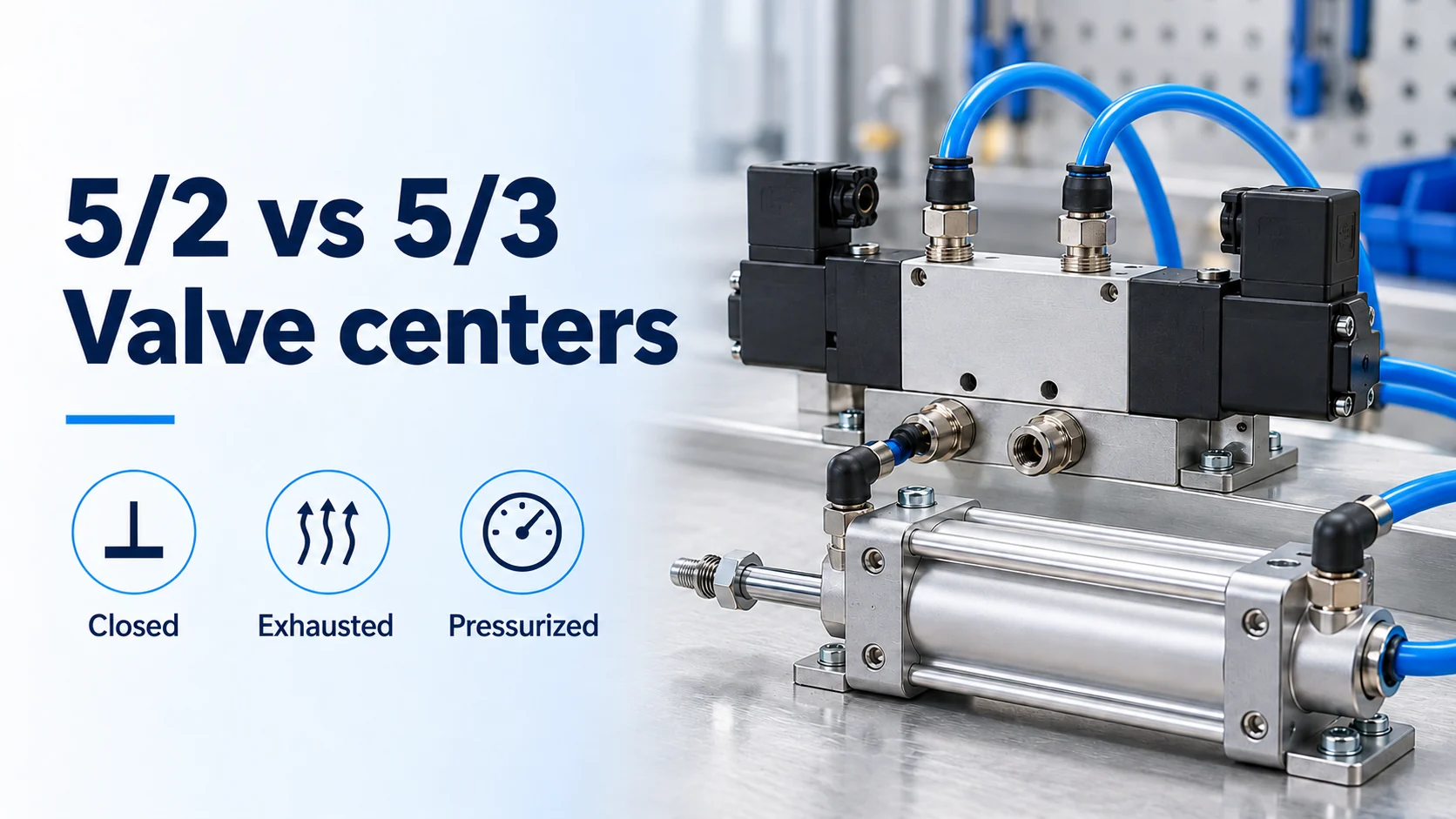
A 5/2 valve has two switching positions and no selectable center; a 5/3 adds a third flow condition. That extra position can block, exhaust or pressurize the cylinder connections, but the resulting piston movement depends on the load, chamber pressure, leakage and components between the valve and cylinder.
For a 5/2 vs 5/3 valve center decision, first specify what must happen when the electrical command disappears while air remains available. A monostable 5/2 returns to its normal flow state; a bistable 5/2 normally keeps its selected state. A spring-centered 5/3 returns to its center configuration. Closed center retains air, exhausted center provides vent paths, and pressurized center supplies both sides. None of these descriptions alone establishes a safe emergency-stop function.
The comparison below applies to conventional double-acting cylinders. For the wider relationship between load, actuator and air supply, start with the pneumatics selection guides.
What changes when the coils switch off?
Compare the valve’s flow state separately from the cylinder’s position. The table assumes working air and any required pilot pressure remain available, the return mechanism functions, and the 5/3 versions are spring-centered. Downstream checks, locks and restrictions can change the chamber behavior.
| Configuration | Flow state after coil removal | Cylinder tendency | Pressure retained or supplied | Principal failure mode | Design check |
|---|---|---|---|---|---|
| Monostable 5/2 | Returns to its normal position: one work port supplied, the other exhausted | Extends or retracts according to the hose connections | One chamber remains supplied | Unexpected movement on signal loss | Trace the normal-state symbol to the actual cylinder ports |
| Bistable 5/2 | Normally retains the last selected flow state | Can continue the commanded stroke | One chamber remains supplied | Spool memory mistaken for piston holding | Check the manufacturer’s power-loss and air-loss behavior |
| Closed-center 5/3 | Main ports blocked | Air compression allows overrun; leakage can cause drift | Chamber air trapped | Load settles or moves despite a centered valve | Evaluate holding needs and provide controlled residual-pressure release |
| Exhausted-center 5/3 | Supply blocked; both work ports connected to exhaust | Restraint decays as chambers vent; gravity or another force can move the load | Pressure falls only through available vent paths | Load moves during venting, or downstream checks retain air | Trace each chamber’s complete release path and control the load |
| Pressurized-center 5/3 | Supply connected to both work ports; exhausts blocked | A single-rod cylinder has an extension force at equal chamber pressure | Both chambers supplied | Unequal piston areas mistaken for force balance | Calculate both chamber forces and include the external load |
The 5 denotes five main ports: supply 1, work ports 2 and 4, and exhausts 3 and 5. The second number counts switching positions. “Center” describes the valve’s flow configuration; it does not locate the piston halfway along the cylinder. Festo’s Pneumatic valves explanation and CPE valve datasheet distinguish these functions and their symbols.
Bistable vs monostable 5/2: what does memory retain?
A bistable valve retains a flow selection; a monostable valve has a defined return state. Neither behavior, by itself, holds a piston at the point where an electrical signal ends.
On a monostable 5/2, removing the signal allows a spring or air-return mechanism to restore the normal position. If air remains available, that position still connects supply to a cylinder chamber. The cylinder can therefore move on de-energization. Whether it extends or retracts follows the plumbing and normal-position symbol, not the phrase “single solenoid.”
A bistable 5/2 normally stays in its selected position after a switching pulse. Air can continue entering the same chamber, so the cylinder can finish its stroke. This is useful when the operating sequence calls for retained direction, but it does not provide a neutral stop state.
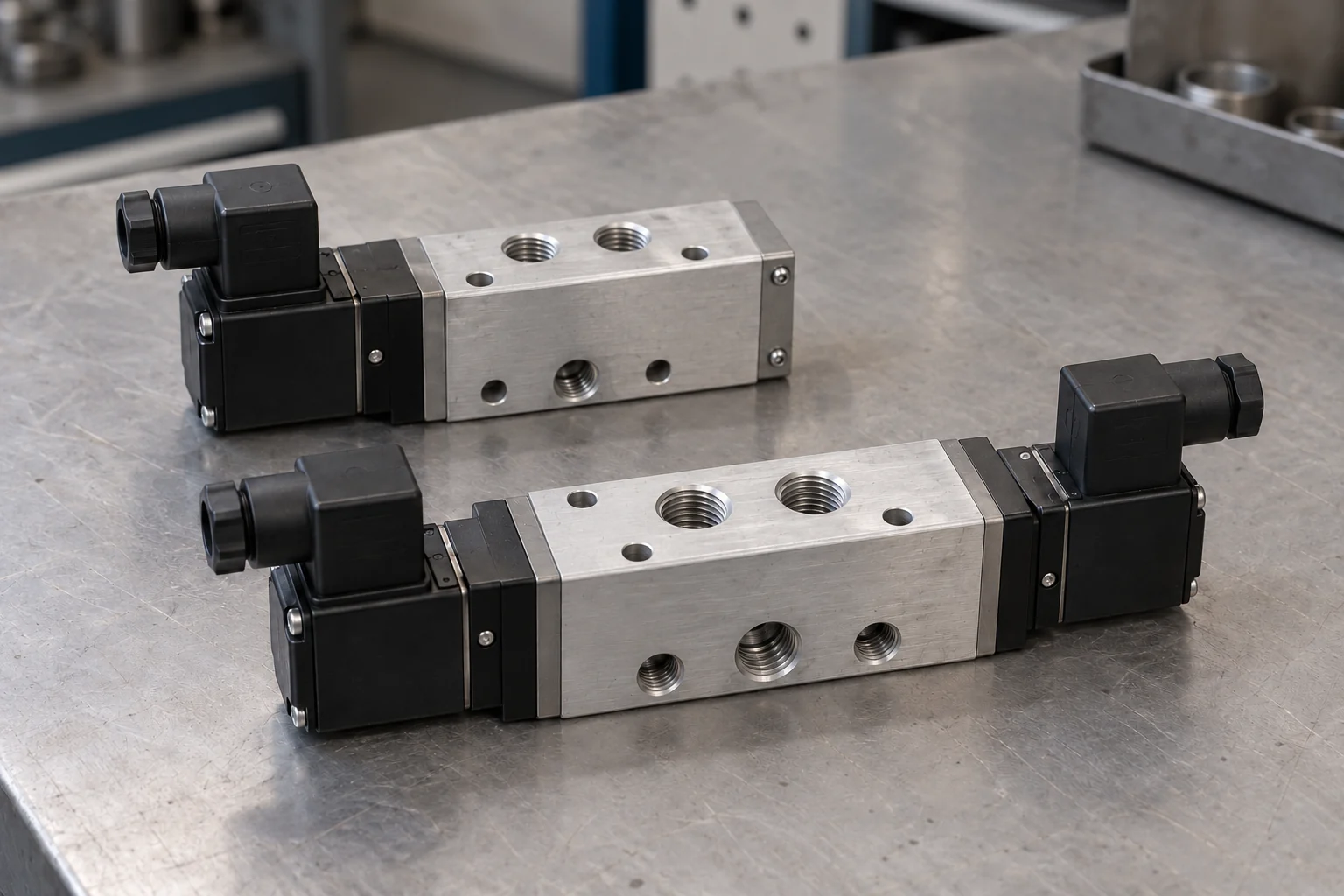
The distinction matters during faults. The SMC SJ-SMX191E manual, section 7.7, separately documents loss of electricity with air present and loss of air before electricity. Its double-solenoid entries leave spool position undefined under the listed interruptions. Use the actual valve’s manual to establish fault behavior rather than extending normal pulse-memory operation into a safety guarantee.
Closed center vs exhausted center: retain air or vent it?
Closed center isolates the work ports; exhausted center connects them to exhaust. The choice changes both the resistance to motion and the way stored pneumatic energy can be released.
Closed center: air acts as a spring
Closing the valve traps air in the tubing and cylinder chambers. A moving load can compress that air before coming to rest, and a change in external load can shift the piston. Leakage through valves, fittings or cylinder seals can then change the pressure balance and cause drift.
SMC’s Hold It Right There, Best Practices 11.0, explains these two limits separately: compressibility affects stopping behavior, while leakage affects position retention over time. A closed-center symbol therefore supports a statement about blocked flow paths, not a promise of zero movement or indefinite load holding.
Where unintended motion could cause crushing, provide suitable independent load restraint as part of the machine’s safety design. Also identify how pressure trapped between the closed valve and actuator will be released under controlled conditions. Venting the upstream supply may leave those chambers pressurized.
Exhausted center: trace the whole path to atmosphere
With a conventional exhausted center, supply port 1 is blocked and work ports 2 and 4 connect to exhaust. If the paths from the chambers are open, chamber pressure falls and pneumatic restraint reduces. A vertical load can move under gravity; a horizontal mechanism can move under an external force.
Venting takes place through the installed tubing, restrictions and exhaust components. Treat the center symbol as the starting point for tracing that route. Check valves or closed stop valves downstream can interrupt it entirely; restrictions can slow the pressure decay. The meter-in and meter-out flow-control guide explains where metering elements sit in these paths.
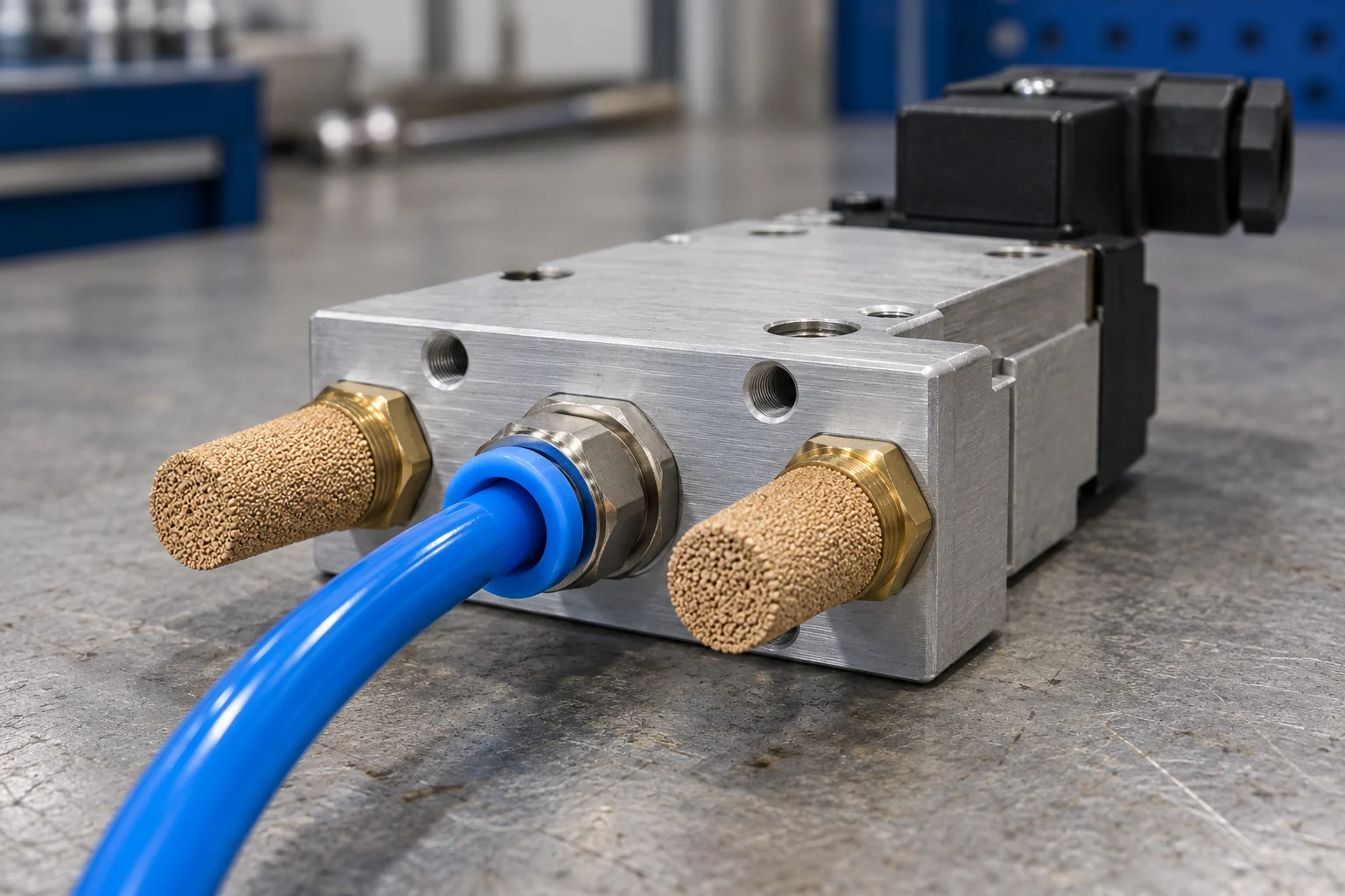
An exhausted valve can coexist with trapped cylinder pressure. In the pilot-operated check arrangement described in Hold It Right There, exhausting the pilot signals closes the checks at the actuator. Air is then retained behind them even though the directional valve is in exhaust center. A release plan must account for the chamber side of those checks.
For manual repositioning or jam clearing, establish a controlled load and a verified safe energy state before access. Selecting exhausted center alone does not establish that state.
Why can pressurized center extend a single-rod cylinder?
Equal pressure produces unequal forces when the effective piston areas differ. A single-rod cylinder has a full piston area on the cap side and a smaller annular area on the rod side. Feeding both chambers at the same pressure leaves a net pneumatic force toward extension.
Using chamber gauge pressures relative to the same atmosphere, the pneumatic force toward extension is:
Fpneumatic = pcapApiston − prod(Apiston − Arod)
Here, Arod is the rod’s cross-sectional area. Pressure in pascals and area in square metres give force in newtons. When both chamber pressures equal p, the relationship simplifies to:
Fpneumatic = pArod, toward extension.
This follows from the pressure-times-area relationship discussed in Hold It Right There. Actual motion also depends on external load, friction and pressure transients. Equal pressure is a defined comparison condition; tubing and restrictions can make the chamber pressures differ during movement.
An equal-area actuator removes this particular area imbalance, but an external load can still disturb the balance. A force-balancing circuit must account for that load and any changes to it. Pressurized center is therefore a circuit choice for a defined force requirement, not a general-purpose pneumatic lock. Record cylinder geometry and load direction using the cylinder selection questions.
Does a 5/3 valve provide an emergency stop?
The center condition is one input to the emergency-stop design. The machine’s risk assessment must determine whether hazardous motion needs to stop, a load needs to remain restrained, pressure needs to be released, or several actions must occur in sequence.
Evaluate these events separately:
| Event | What must be established |
|---|---|
| Electrical command disappears; air remains | Which flow state the valve reaches, and what force it produces at the cylinder |
| Working air supply disappears | Which volumes retain pressure, and how the load behaves as pressure changes |
| Pilot pressure disappears | Whether the valve can shift or return with the remaining energy |
| Air and electrical power return | Whether the initial spool state and chamber pressures permit an unexpected stroke |
A valve that uses air force to return needs the required pilot pressure. An externally piloted valve may have a pilot source whose loss or restoration occurs separately from the main supply. Confirm the reset construction, pilot arrangement and minimum operating pressure in the selected component’s documentation; then validate the sequence on the complete machine.
Vertical loads and maintenance need distinct provisions
For a vertical actuator, releasing pressure may remove the force supporting the load. Retaining pressure also leaves stored energy and depends on the retaining components. Choose load restraint with the required failure behavior and holding capacity, and coordinate its application and release with the pneumatic circuit.
Mechanical holding locks and dynamic brakes have different duties. The locking-actuator circuit discussed in Hold It Right There requires the actuator to stop before the lock engages. Verify whether a selected device is intended to hold a stationary load or absorb motion before using it for a stopping function.
For servicing covered by U.S. OSHA 29 CFR 1910.147, section (b) distinguishes energy-isolating devices from push buttons and other control-circuit devices. Sections (d)(3)–(6) address isolation, lockout/tagout application, stored energy and verification. Apply the machine-specific energy-control procedure, including restraint or release of hazardous stored energy and verification before work begins.
Plan the restart as carefully as the stop
Reintroducing pressure to one cylinder chamber while the opposite chamber has little backpressure can produce abrupt movement. Releasing a mechanical lock before the supporting pressure or force balance is established can also allow the load to move. Define the order of air admission, valve commands and restraint release, then check it against the actual load and operating conditions.
What should be recorded before selecting the valve?
Write down the required motion, restraint and release behavior before choosing a center symbol. Use this checklist to turn the comparison into a circuit review:
- Actuator and load: single-rod or equal-area geometry, orientation, load direction, gravity effects and other external forces.
- Normal operation: required extension and retraction paths, monostable return or bistable memory, and the actual hose-to-port mapping.
- Stop requirement: allowed travel after the command, acceptable drift, holding duration, and whether load restraint or controlled pressure release is required.
- Valve construction: exact flow symbol, spring or air return, internal or external pilot source, and specified pilot-pressure requirement.
- Intervening components: pilot-operated checks, speed controls, stop valves, locks and the release path for every trapped volume.
- Loss and restoration sequence: electricity, working air and pilot air considered separately, including which source disappears or returns first.
- Validation: acceptance criteria for stopping, holding, controlled release and restart under the machine’s actual operating conditions, with the required safety measures in place.
Technical references for the valve comparison are Festo’s Pneumatic valves and CPE datasheet (September 2026 edition, center symbols on pages 42–43), SMC’s Hold It Right There (Best Practices 11.0, 2018, pages 2–6), and the SMC SJ-SMX191E installation manual (section 7.7). The OSHA reference below applies to covered U.S. servicing and maintenance.